


8 Agilent E1538A Enhanced Frequency/Totalize/PWM SCP
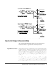
Recommended Signal Connections
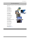
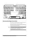
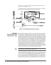
Figure 5 shows the recommended method of wiring digital I/O channels, as
well as the maximum voltage limitations for the E1538A.
Figure 5 shows the shields connected directly to the E1415 ground. This is
to limit potential noise on the digital wiring from affecting low-level analog
channel wiring within the Terminal Module.
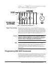
Note The G (analog guard) terminals are connected through 10K Ohm resistors
to chassis ground. To connect the shields directly to chassis ground on the
E1415 and the E1419 Option 12 Terminal Module, install the
guard-to-ground jumpers for the E1538 channels
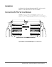
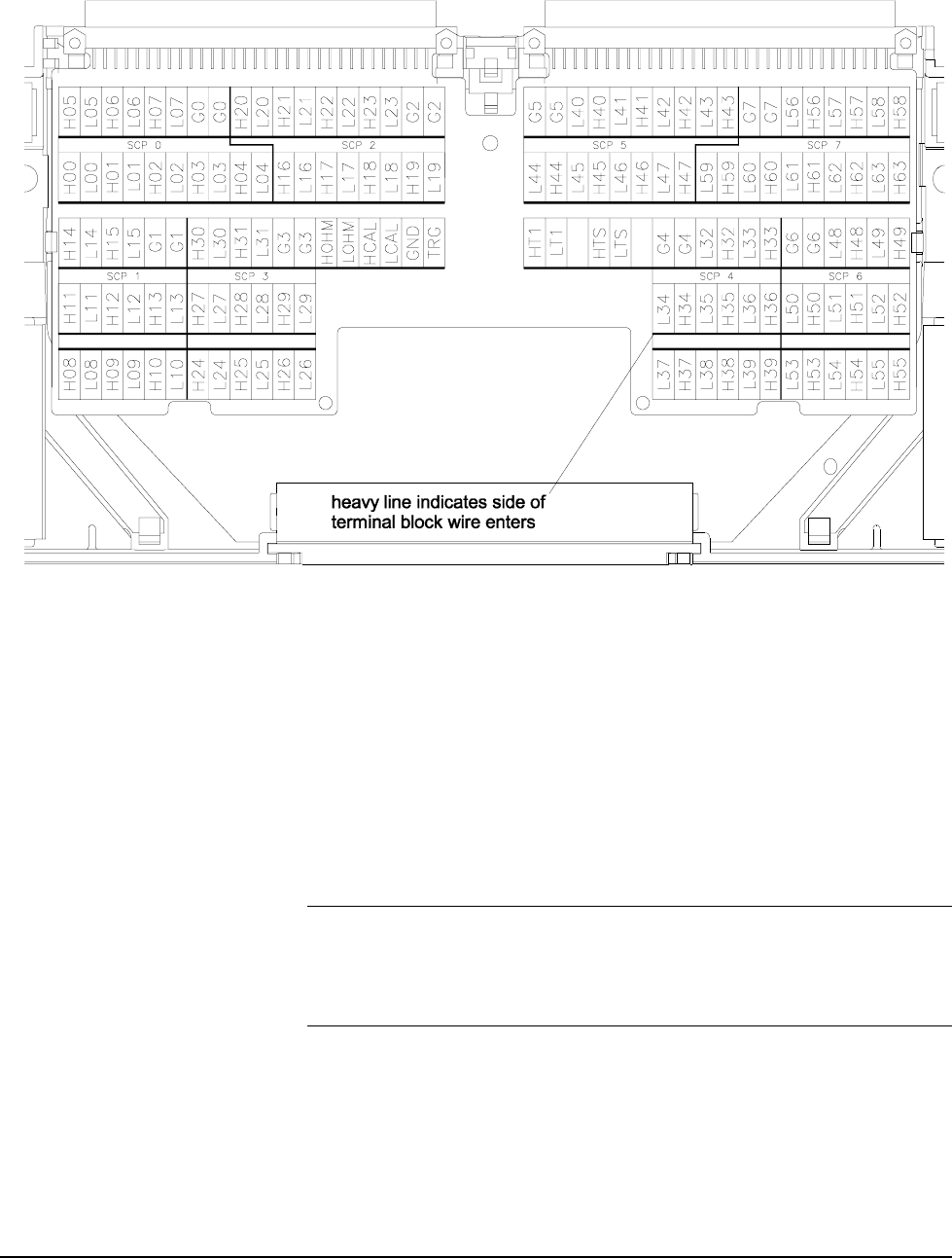
Figure 4. E1419A Option 11 Terminal Module Connections