


10 Control Surface & Rear Panel
01V96i—Owner’s Manual
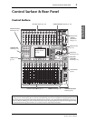
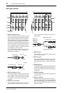
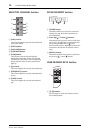
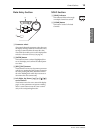
AD Input Section
1 INPUT connectors A/B
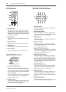
INPUT A connectors are balanced XLR-3-31-type
connectors that accept line-level and microphone
signals. Each of the phantom [+48V] switches on
the rear panel turns on or off the +48V phantom
power feed to the corresponding input. INPUT B
connectors are balanced TRS phone-type connec-
tors that accept line-level and microphone signals.
The nominal signal level of both types of connec-
tors ranges from –60 dB to +4 dB. Phantom power
is not supplied to these connectors.
If you connect cables to INPUT A and INPUT B
connectors of the same number, only the signal
from INPUT B is effective.
2 INPUT connectors 13–16
These balanced TRS phone-type connectors accept
line-level signals. The nominal signal level ranges
from –26 dB to +4 dB. INPUT 15 & 16 connectors
are available only when the AD 15/16 button is
turned off.
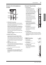
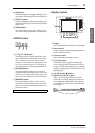
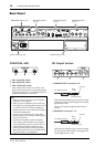
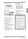
3 INSERT I/O connectors
These unbalanced TRS phone-type connectors are
used for channel insert ins and outs. Use a split
cable to insert an external effects processor to AD
input channels.
4 PAD switches
These switches turn on or off the 20 dB pad (atten-
uator) for each AD Input.
5 GAIN controls
These controls adjust input sensitivity for each AD
Input. Input sensitivity is –16 dB to –60 dB when
the Pad is off, and +4 dB to –40 dB when the Pad is
on.
6 PEAK indicators
These indicators light up when the input signal level
is 3 dB below clipping. Adjust the Pad switch and
GAIN control so that the indicator rarely lights up
at signal peak.
7 SIGNAL indicators
These indicators light up when the input signal level
exceeds –34 dB.
8 AD15/16 selector
This button selects AD Input Channel 15 and 16
signals. When the button is turned on (pushed in),
the 2TR IN signals (page 17) are selected. When the
button is turned off (raised), the INPUT 15 and 16
signals are selected.
PEAK
SIGNAL
PEAK
SIGNAL
PEAK
SIGNAL
PEAK
SIGNAL
PEAK
SIGNAL
PEAK
SIGNAL
PEAK
SIGNAL
PEAK
SIGNAL
PEAK
SIGNAL
PEAK
SIGNAL
PEAK
SIGNAL
CH15
/
16
2TR IN
+4
-26
GAIN
+4
-26
GAIN
+4
-26
GAIN
GAIN
+4
-26
GAIN
20dB
-16
-60
GAIN
20dB
-16
-60
GAIN
20dB20dB20dB20dB20dB20dB20dB
-16
-60
GAIN
-16
-60
GAIN
-16
-60
GAIN
-16
-60
GAIN
-16
-60
GAIN
-16
-60
GAIN
-16
-60
PAD
A
B
A
B
A
B
A
B
A
B
A
B
A
B
A
B
A
B
16
1513
121110943215
14
INSERT I
/
O INSERT I
/
O INSERT I
/
O INSERT I
/
O INSERT I
/
O INSERT I
/
O INSERT I
/
O INSERT I
/
O INSERT I
/
O
CH1-4
INPUT
(BAL)
INSERT
OUTIN
(UNBAL)
13 14 15 16
1
3
4
5
6
7
8
2
1/4" TRS phone plug
Ring (cold)
Sleeve (ground)
Tip (hot)
Male XLR plug
1 (ground)
2 (hot)
3 (cold)
1/4" phone
plug
1/4" phone plug
Sleeve (ground)
Tip (send)
Sleeve
(ground)
Connect to
INSERT jack
Tip (return)
1/4" phone plug
Tip (send)
Ring (return)
Sleeve (ground)
From processor’s output
To processor’s input