


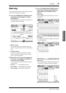

Wordclock Connections and Settings 27
01V96i—Owner’s Manual
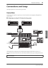
Connections
and Setup
Wordclock Connections
and Settings
About Wordclock
Digital audio equipment must be synchronized when
digital audio signals are transferred from one device to
another. Even if both devices use identical sampling
rates, digital signals may not transfer correctly, or audi-
ble noise or unwanted clicks may occur if the digital
audio processing circuits inside each digital audio
device are not synchronized with each other.
Wordclocks are signals that enable digital audio pro-
cessing circuits to synchronize with each other. In a
typical digital audio system, one device operates as the
wordclock master, transmitting wordclock signals, and
the other devices operate as wordclock slaves, synchro-
nizing to the wordclock master.
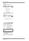
If you are digitally connecting the 01V96i to other
equipment, you must decide which device to use as the
wordclock master and which devices to use as slaves,
then set up all the devices accordingly. The 01V96i can
be used as the wordclock master running at either
44.1 kHz, 48 kHz, 88.2 kHz, or 96 kHz, or slaved to an
external wordclock source.
Wordclock Connections
To establish wordclock synchronization between the
01V96i and external devices, you can distribute word-
clock signals independently via dedicated cables, or you
can use clock information derived from digital audio
connections.
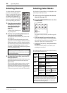
The WORD CLOCK IN and OUT connectors transmit
and receive wordclock signals independently on the
01V96i. The following examples show two ways in
which wordclock signals can be distributed and received
via the WORD CLOCK IN and OUT connectors.
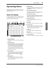
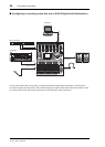
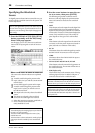
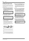
• Daisy Chain Distribution
In this example, the wordclock signal is distributed
in a “daisy-chain” fashion, with each device feeding
the wordclock signal from the wordclock out con-
nector on to the wordclock in connector of the next
device. This method of distribution is not recom-
mended for larger systems.
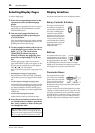
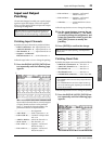
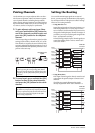
• Star Distribution
In this example, a dedicated wordclock distribution
box is used to supply wordclock signals from the
wordclock master to each wordclock slave individ-
ually.
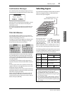
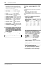
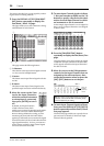
If the external devices do not have wordclock in and
out connectors, you can use the clock information
included in the digital audio signals. In this case,
digital audio signals and wordclock signals are
transferred via the 2TR OUT DIGITAL and 2TR IN
DIGITAL jacks or via the digital I/O card installed
in the rear panel slot.
WC IN
(BNC)
WC OUT
(BNC)
WC OUT (BNC)
WC IN
(BNC)
WC IN
(BNC)
WC OUT
(BNC)
Wordclock
master
Device A
Wordclock
slave
Device B
Wordclock
slave
Device C
Wordclock
slave
WC OUT
(BNC)
WC IN (BNC) WC IN (BNC) WC IN (BNC) WC IN (BNC)
Wordclock
master
Device A
Wordclock
slave
Device B
Wordclock
slave
Device D
Wordclock
slave
Device C
Wordclock
slave
Wordclock
distribution box
SOLO SOLO
ON ON
SOLO
ON
SOLO
ON
SOLO
ON
SOLO
ON
SOLO
ON
SOLO
ON
SOLO
ON
SOLO
ON
SOLO
ON
SOLO
ON
SOLO
ON
SOLO
ON
SOLO
ON
SOLO
ON
SOLO
ON
SOLO
ONON
PEAK
SIGNAL
PEAK
SIGNAL
PEAK
SIGNAL
PEAK
SIGNAL
PEAK
SIGNAL
PEAK
SIGNAL
PEAK
SIGNAL
PEAK
SIGNAL
PEAK
SIGNAL
PEAK
SIGNAL
PEAK
SIGNAL
PEAK
SIGNAL
PEAK
SIGNAL
PEAK
SIGNAL
1-16 17-32 MASTERREMOTE
LAYER
SEL SEL SEL SEL SEL SEL SEL SEL SEL SEL SEL SEL SEL SEL SEL SEL SEL SELSEL
ST IN
ENTER
STEREO
DEC INC
SOLO CLEAR
RECALL
STORE
SCENE MEMORY
PHONES
MONITOR
OUT
MONITOR
2TR IN
CH15
/
16
2TR IN
LEVEL
PHONES
LEVEL
0
10
0
10
+4
-26
GAIN
+4
-26
GAIN
+4
-26
GAIN
GAIN
+4
-26
GAIN
20dB
-16
-60
GAIN
20dB
-16
-60
GAIN
20dB20dB20dB20dB20dB20dB20dB20dB20dB20dB
-16
-60
GAIN
-16
-60
GAIN
-16
-60
GAIN
-16
-60
GAIN
-16
-60
GAIN
-16
-60
GAIN
-16
-60
GAIN
-16
-60
GAIN
-16
-60
GAIN
-16
-60
PAD
FADER MODE
DISPLAY ACCESS
AUX
1
AUX
1
AUX
2
AUX
3
AUX
4
AUX
5
AUX
6
AUX
7
AUX
8
BUS
1
BUS
2
BUS
3
BUS
4
BUS
5
BUS
6
BUS
7
BUS
8
AUX
2
AUX
3
AUX
4
AUX
8
AUX
7
AUX
6
AUX
5
HOME (METER)
DYNAM ICS
EQ EFFECT VIEW
PATCH
UTILITYMIDISCENE
DIO/SETUP
/ INSERT/
DELAY
PAN/
ROUTING
PAIR /
GROUP
A
B
A
B
A
B
A
B
A
B
A
B
A
B
A
B
A
B
A
B
A
B
A
B
16
1513
121110987643215
14
INSERT I
/
O INSERT I
/
O INSERT I
/
OINSERT I
/
O INSERT I
/
O INSERT I
/
OINSERT I
/
OINSERT I
/
OINSERT I
/
O INSERT I
/
O INSERT I
/
O INSERT I
/
O
L
R
IN OUT
2TR
-10dBV (UNBAL)
PHANTOM +48V
CH9-12CH5-8CH1-4
INPUT
(BAL)
INSERT
OUTIN
(UNBAL)
ST IN 1 ST IN 2
USER DEFINED
KEYS
12
34
56
78
55
5
+10
5
1010
10
1515
15
2020
20
303030
30
4040
40
5050
50
6060
7070
20
30
40
40
50
50
60
70
00
5
10
15
20
0
0
5
+10
5
10
15
30
20
30
40
40
50
50
60
70
20
30
40
40
50
50
60
70
20
30
40
40
50
50
60
70
20
30
40
40
50
50
60
70
20
30
40
40
50
50
60
70
15
0
5
10
15
20
0
5
+10
5
10
0
30
15
5
10
15
20
0
5
+10
5
10
0
30
15
5
10
15
20
0
5
+10
5
10
0
30
15
5
10
15
20
0
5
+10
5
10
0
30
15
20
30
40
40
50
50
60
70
30
15
20
30
40
40
20
30
40
20
30
40
20
30
40
50
50505050
20
30
40
50
20
30
40
50
60
70
40
50
60
70
40
50
60
70
40
50
60
70
40
50
60
70
40
50
60
70
40
50
60
70
40
50
60
70
30
15
5
10
15
20
0
5
+10
5
10
0
5
10
15
20
0
5
+10
5
10
0
5
10
15
20
0
30
5
10
15
20
0
30
5
10
15
20
0
30
5
10
15
20
0
30
5
10
15
20
0
303030
5
10
15
20
0
5
10
15
20
0
5
10
15
20
0
5
+10
5
10
0
15
5
+10
5
10
0
15
5
+10
5
10
0
15
5
+10
5
10
0
15
20
30
40
50
15 15
20
30
40
50
15
5
+10
5
10
0
5
+10
5
10
0
5
+10
5
10
0
5
+10
5
10
0
123456
123456
7
8 9 10 11 12
7
8 9 10 11 12
13 14 15 16
13 14 15 16
32313029282726252423222120191817
STEREO
13 14 15 16
OVER
0
-3
-6
-9
-12
-15
-18
-24
-30
-36
-48
HIGH
HIGH-MID
LOW-MID
LOW
Q
FREQUENCY
GAIN
Digital I/O
card
External device
Digital audio signal
+
Wordclock signal