


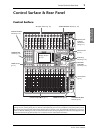

12 Control Surface & Rear Panel
01V96i—Owner’s Manual
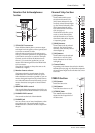
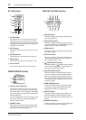
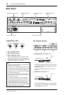
ST IN Section
1 [ST IN] button
This button selects an ST IN channel pair (ST IN
Channels 1 & 2 or 3 & 4) which you can control
using the buttons and controls in the ST IN section.
The indicators to the right of the button indicate the
available ST IN channels.
2 [SEL] buttons
These buttons select the ST IN channel you want to
control.
3 [SOLO] buttons
These buttons solo the selected ST IN channels.
4 [ON] buttons
These buttons turn the ST IN channels on or off.
5 Level controls
These controls adjust the ST IN channel levels.
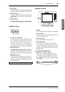
FADER MODE Section
1 [AUX 1]–[AUX 8] buttons
These buttons enable you to select the Aux Send
you wish to control. Pressing one of these buttons
switches the Fader mode (see page 22), and displays
the corresponding Aux page. (The selected button’s
indicator lights up.)
You can now adjust the send level of signals routed
from Input Channels to the corresponding Aux
buses by using the faders.
2 [HOME] button
This button recalls Meter pages that display Input
Channel levels or Output Channel (Bus Out, Aux
Out, Stereo Out) levels (see page 23).
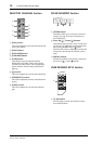
DISPLAY ACCESS Section
1 [SCENE] button
This button displays a Scene page, enabling you to
store and recall Scenes.
2 [DIO/SETUP] button
This button displays a DIO/Setup page, enabling
you to set up the 01V96i, including digital input and
output setup and remote control setup.
3 [MIDI] button
This button displays a MIDI page, enabling you to
make MIDI settings.
4 [UTILITY] button
This button displays a Utility page, enabling you to
use the internal oscillators and view information
about installed optional cards.
5 [ /INSERT/DELAY] button
This button displays a /INS/DLY page, enabling
you to switch the signal phase, set the signal to be
inserted, or set the delay parameters.
6 [PAN/ROUTING] button
This button displays a Pan/Route page, enabling
you to select a Bus to which the selected channel
signal is routed, adjust the selected channel pan set-
tings, adjust the level of signals routed from Buses
1–8 to the Stereo Bus, and adjust the stereo or sur-
round pan settings.
7 [PAIR/GROUP] button
This button displays a Pair/Group page, enabling
you to create or cancel channel pairs and group
multiple channel faders or [ON] buttons.
8 [PATCH] button
This button displays a Patch page, enabling you to
patch input signals and Bus Out signals to Input
channels, or patch signals to the desired output con-
nectors.
9 [DYNAMICS] button
This button displays a Dynamics page, enabling you
to control channel gates and compressors.
SOLO
ON
SOLO
ON
SEL SEL
ST IN
ST IN 1 ST IN 2
1
2
3
4
5
FADER MODE
AUX
1
AUX
2
AUX
3
AUX
4
AUX
8
AUX
7
AUX
6
AUX
5
HOME (METER)
1
2
DISPLAY ACCESS
DYNAMICS
EQ EFFECT VIEW
PATCH
UTILITYMIDISCENE
DIO/SETUP
/ INSERT/
DELAY
PAN/
ROUTING
PAIR/
GROUP
1 2 3
9
0 A B
4
5
6
8
7
UTILITYMIDISCENE
DIO/SETUP