


22 Operating Basics
01V96i—Owner’s Manual
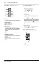
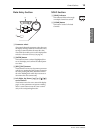
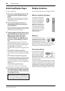
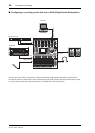
Selecting Channels
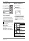
To select a channel on the 01V96i,
press the corresponding [SEL]
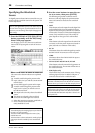
button. To adjust the Pan and EQ
settings, use the rotary controls in
the SELECTED CHANNEL sec-
tion. To select a channel on pages
that cover multiple channels, press
the corresponding [SEL] button.
1. Press the corresponding
LAYER button to select a
layer that includes the
desired channel (see
page 21).
To select ST IN channels, press
the [ST IN] button.
2. Use the corresponding [SEL] button to
select the desired channel.
The channel is selected and the [SEL] button indi-
cator lights up.
The Channel’s ID and short name appear in the
upper-left corner of the display. If the currently-dis-
played page contains a relevant channel parameter,
the cursor moves to that parameter automatically. If
the currently-displayed page contains no such
parameter, a page that does contain such a parame-
ter is selected automatically.
3. To select the Stereo Out, press the STE-
REO [SEL] button.
Repeatedly pressing the STEREO [SEL] button tog-
gles between the Stereo Out left and Stereo Out
right channels.
If the currently-displayed page contains a relevant
Stereo Out parameter, the cursor moves to that
parameter automatically. If the currently-displayed
page contains no such parameter, a page that does
contain such a parameter is selected automatically.
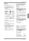
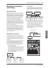
Selecting Fader Modes
The function of channel faders (1–16) depends on the
selected Layer and Fader mode.
1. Select a layer that includes the desired
channel (see page 21).
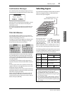
2. Press the FADER MODE buttons to select
a Fader mode.
The button indicators identify the following Fader
modes:
• When the [HOME] button indicator lights up:
You can use channel faders to control Input Chan-
nels and ST IN Channel levels or Output Channels
(Aux Out 1–8, Bus Out 1–8) master levels.
• When one of the [AUX1]–[AUX8] button indica-
tors light up:
You can use channel faders to control the corre-
sponding Aux Send level.
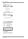
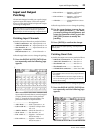
The following table shows the channel fader functions
for each Layer and Fader mode.
Tip: For paired Input or Output Channels, the channel
for which you pressed the [SEL] button is selected, and
its indicator lights up. The [SEL] button indicator of
the paired partner flashes.
HIGH
HIGH-MID
LOW-MID
LOW
Q
FREQUENCY
GAIN
LAYER
buttons
Fader Mode
Channel Strip Fader
1–8 9–16
[1–16]
button
[HOME] button Input Channel 1–16 level
[AUX1]–[AUX8]
buttons
Input Channel 1–16 Aux
Send level
[17–32]
button
[HOME] button Input Channel 17–32 level
[AUX1]–[AUX8]
buttons
Input Channel 17–32 Aux
Send level
[REMOTE]
button
[HOME] button
Operation depends on the
selected target.
[AUX1]–[AUX8]
buttons
[MASTER]
button
[HOME] button
Aux Send
master 1–8
output level
Bus Out
master1–8
output level
[AUX1]–[AUX8]
buttons
No operation
Note: You cannot select the [AUX1]–[AUX8] buttons
while the Master layer is selected. If you switch to the Mas-
ter layer while one of the [AUX1]–[AUX8] button indica-
tors is lit, the indicator automatically turns off and the
[HOME] button indicator lights up.
FADER MODE
AUX 1 AUX 2 AUX 3 AUX 4
AUX 8AUX 7AUX 6AUX 5
HOME (METER)