


34 Tutorial
01V96i—Owner’s Manual
This section describes how to route signals by combin-
ing the above two routing methods.
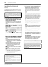
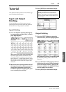
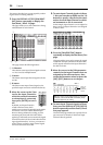
1. Press the DISPLAY ACCESS [PAN/ROUT-
ING] button repeatedly to display the
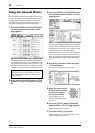
Pan/Route | Rout1-16 page.
This page enables you to select a Bus Out as the sig-
nal destination for each channel.
This page contains the following buttons:
1 1–8 buttons
These buttons route Input Channel signals to Buses
1–8. You can select multiple buttons.
2 S button
This button routes Input Channel signals to the Ste-
reo Bus.
3 D button
This button routes Input Channel signals to the
specified output connectors and channels directly.
2. Move the cursor to the S but-
ton for the Input Channel to
which the musical instrument
or microphone is connected,
then press [ENTER] to turn it
off.
By default, each Input Channel is
routed to the Stereo Bus, which
enables you to monitor the signals from the MON-
ITOR OUT connectors and the PHONES jack.
However during multitrack recording, or when
monitoring the sound with the DAW’s effects
applied, you will usually want to monitor the signals
returned from the recorder or DAW rather than the
input signals themselves. To do so, you must turn
off the S button so that the Input Channel signals
will not be sent to the Stereo Bus.
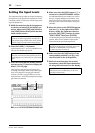
3. To route Input Channel signals via Buses
1–8 to your recorder or DAW, use the 1–8
buttons to specify a Bus Out as the desti-
nation for each Input Channel to which
an instrument or mic is connected.
In this example, Input Channels 1–4 are assigned to
Buses 1 and 2, and Input Channels 5–8 are assigned
to Buses 3 and 4.
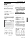
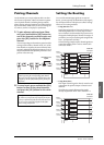
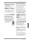
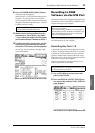
4. Press the [PAN/ROUTING] button
repeatedly to display the Pan/Route | Pan
page.
This page enables you to set the panpots for signals
routed from the Input Channels to the Stereo Bus,
and for signals routed from the Input Channels to
the odd-even buses.
5. Move the cursor to the PAN parameter
controls for the Input Channels that are
assigned to the odd-even buses, then
rotate the Parameter wheel or press the
[INC]/[DEC] buttons to set the pan.
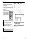
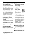
6. To route Input Channel signals to Direct
Outs, press the DISPLAY ACCESS [PATCH]
button repeatedly until the Patch | Direct
Out page appears.
The Direct Out page enables you to specify the out-
put connectors or channels to which each Input
Channel is directly patched.
1
3
2
Tip: You can also use the [SEL] buttons to select Input
Channels, and the SELECTED CHANNEL [PAN]
control to adjust the pan setting.
Cursor on
the PAN
parameter
control