


Adjusting the Monitor Levels from the DAW 41
01V96i—Owner’s Manual
Tutorial
Adjusting the Monitor
Levels from the DAW
The audio being played back from the DAW can be
returned to the 01V96i’s Input Channels and moni-
tored via the MONITOR OUT jacks or PHONES jack.
Normally, the signal of the DAW’s stereo bus is sent to
an 01V96i Input Channel for monitoring. However
when overdubbing, you might need to monitor with a
balance that’s different than the mix balance of the
song. In this situation, the signal from each DAW track
can be returned to a separate Input Channel, and the
balance adjusted on the 01V96i. Here we’ll explain the
procedure for sending the signals of DAW tracks 1–8 to
the 01V96i’s Input Channels 17–24 and adjusting the
monitor levels.
1. Use a USB cable to connect your com-
puter to the 01V96i.
2. Start up your DAW, and set it to use the
Yamaha Steinberg USB Driver.
If you’re using the included Cubase AI, set the fol-
lowing items.
• From the menu bar, choose “Devices” → “Device
Settings,” then click VST Audio System. As the
ASIO driver, choose “Yamaha Steinberg USB
ASIO” (Windows) / “Yamaha 01V96i” (Mac).
• From the “Device” menu, choose “VST Connec-
tions.” In the Input tab, choose [Add Bus], set “Con-
figuration” to Mono and “Number” to 8, and click
[OK] to create sixteen new monaural inputs. For
each newly created “Mono Out 1–8,” set the device
port to “01V96i 1–8” respectively.
For details on other DAW settings, refer to the
owner’s manual of your DAW.
3. In the DAW, select “01V96i 1–8” respec-
tively as the output port of tracks 1–8.
If you’re using Cubase AI, select the name of the
output ports you created in step 2 (by default these
will be Mono Out 1–8).
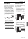
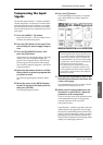
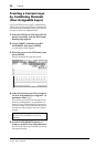
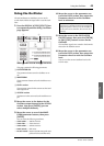
4. Press the DISPLAY ACCESS [PATCH] but-
ton repeatedly until the Patch | In Patch
page appears.
5. Move the cursor to INPUT 17–24, and use
the Parameter wheel (or [INC]/[DEC]) to
select USB IN 1–8 respectively.
6. Press the LAYER [17–32] button.
Input Channel Layer 17–32 is selected for control
from the channel strip section.
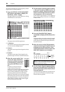
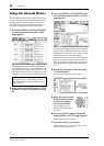
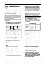
7. Press the DISPLAY ACCESS [PAN/ROUT-
ING] button repeatedly until the
Pan/Route | Rout17-STI page appears.
8. For each Input Channel 17–24, make sure
that the S button is on and the 1–8 but-
tons are off, and use the PAN section to
adjust the panning of the monitor signals
as necessary.
Tip: Controlling Input Channel 17–32 Pan settings,
faders, and the [ON] buttons will affect the monitoring
signal, but will not affect the signal recorded to the
DAW.