


Input and Output Patching 29
01V96i—Owner’s Manual
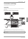
Connections
and Setup
Input and Output
Patching
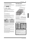
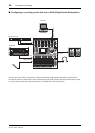
The 01V96i is designed to enable you to patch (assign)
signals to Inputs and Outputs. This section explains
how to view the signals patched to Inputs and Outputs
and change the assignment.
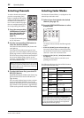
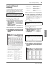
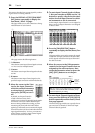
Patching Input Channels
By default, the Input Channels are patched as follows:
• INPUT connectors 1–16....Input Channels 1–16
• ADAT IN channels 1–8......Input Channels 17–24
• Slot channels 1–8.................Input Channels 25–32
• Outputs 1–2 of Internal
Effects Processor 1–4 .........ST IN Channels 1–4
Follow the steps below to view or change the patching.
1. Press the DISPLAY ACCESS [PATCH] but-
ton repeatedly until the following page
appears.
Inputs and Slot channels that are currently assigned
to Input Channels are shown in the parameter
boxes (
1) beneath the channel numbers. The
parameter indicators are explained below:
• – ...................................No assignment
• AD1–AD16 ...............INPUT connectors 1–16
• USB 1–USB 16..........TO HOST USB port chan-
nels 1–16
• ADAT1–ADAT8 ......ADAT IN channels 1–8
• SL-01–SL-16..............Slot channels 1–16
• FX1-1–FX1-2............Outputs 1–2 of Internal
Effects Processor 1
• FX2-1–FX2-2............Outputs 1–2 of Internal
Effects Processor 2
• FX3-1–FX3-2 ............Outputs 1–2 of Internal
Effects Processor 3
• FX4-1–FX4-2 ............Outputs 1–2 of Internal
Effects Processor 4
• 2TD-L/R.....................2TR IN DIGITAL L/R con-
nectors
Follow the steps below to view or change the patching.
2. Use the cursor buttons to move the cur-
sor to a patch parameter (
1) for which
you want to change the assignment, and
rotate the Parameter wheel or press the
[INC]/[DEC] buttons to modify the
patching.
3. Press [ENTER] to confirm the change.
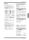
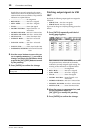
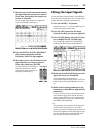
Patching Omni Outs
By default, the output connectors are patched as follows:
• OMNI OUT connectors 1–4.... Aux Out 1–4
• ADAT OUT channels 1–8......... Bus Out 1–8
• Slot channels 1–8........................ Bus Out 1–8
• Slot channels 9–16...................... Bus Out 1–8
• 2TR DIGITAL connectors........ Stereo Out L & R
Follow the steps below to view or change the patching.
1. Press the DISPLAY ACCESS [PATCH] but-
ton repeatedly until the following page
appears.
Tip: If the data from a connected instrument fails to be
input, or if you are unable to monitor the signal at the
desired output, check the I/O patching, as explained below:
1
Tip: To restore the default patching, recall Input Patch
memory #00.
Tip:
• The STEREO OUT connectors always output the Stereo
Bus signals.
• The MONITOR OUT connectors output monitor sig-
nals or the 2TR IN signals, depending on the Monitor
Source selector setting.
1