


Control Surface 11
01V96i—Owner’s Manual
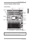
Control Surface
& Rear Panel
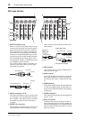
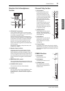
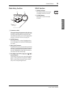
Monitor Out & Headphones
Section
1 2TR IN/OUT connectors
These unbalanced RCA phono connectors input
and output line-level signals, and are typically used
to connect an external recorder.
When the AD15/16 selector in the AD Input sec-
tion (
8) is turned on (pushed in), the signals input
at the 2TR IN connectors are routed to AD Input
Channels 15 and 16. When the Monitor Source
selector (
2) is turned on (pushed in), you can
monitor the 2TR IN signals from the MONITOR
OUT connectors.
The 2TR OUT signals are always the same as the
STEREO OUT signals.
2 Monitor Source selector
This button selects the signals output from the
MONITOR OUT connectors on the rear panel.
When this button is turned on (pushed in), you can
monitor the signals input from the 2TR IN connec-
tors. When the button is turned off (raised), you can
monitor the Stereo Out signals or soloed channel
signals.
3 MONITOR LEVEL control
This control adjusts the monitoring level of the sig-
nals output from the MONITOR OUT connectors.
4 PHONES LEVEL control
This control sets the level of the PHONES.
5 PHONES jack
You can connect a set of stereo headphones to this
stereo phone jack. The signals output from the
MONITOR OUT connectors are also output from
this jack.
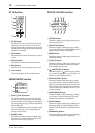
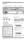
Channel Strip Section
1 [SEL] buttons
These buttons enable you to
select desired channels. The
[SEL] button indicator for the
currently-selected channel lights
up. The channel selected by each
[SEL] button depends on the
layer selected in the LAYER sec-
tion (see page 13).
These buttons also allow you to
create or cancel channel pairs,
and add channels to (or remove
them from) Fader, Mute, EQ, and
Compressor groups.
2 [SOLO] buttons
These buttons solo the selected
channels. The [SOLO] button
indicator of the currently-soloed
channel lights up.
3 [ON] buttons
These buttons turn the selected
channels on or off. The [ON]
button indicators for On chan-
nels light up.
4 Channel faders
Depending on the button selected in the FADER
MODE section (see page 12), these faders adjust the
selected channel input levels or the Bus Out or Aux
Out levels.
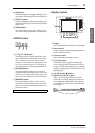
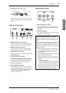
STEREO Section
1 [SEL] button
Selects the Stereo Out.
2 [ON] button
Turns the Stereo Out on or off.
3 [STEREO] fader
This 100mm motorized fader
adjusts the final output level of
the Stereo Out.
PHONES
MONITOR
OUT
MONITOR
2TR IN
LEVEL
PHONES
LEVEL
0
10
0
10
L
R
IN OUT
2TR
-10dBV
(UNBAL)
PHANTOM +48V
CH9-12CH5-8
1
2
3
4
5
SOLO
ON
SEL
AUX 1
40
50
60
70
30
5
10
15
20
0
20
30
40
50
15
5
+10
5
10
0
1
1
17
1
2
3
4
ON
SEL
5
10
15
20
30
40
50
60
70
0
STEREO
1
2
3