


16 Control Surface & Rear Panel
01V96i—Owner’s Manual
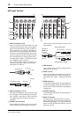
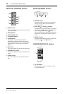
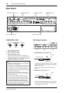
Rear Panel
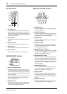
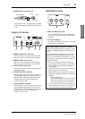
PHANTOM +48V
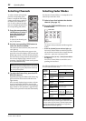
1 CH1–4 ON/OFF switch
2 CH5–8 ON/OFF switch
3 CH9–12 ON/OFF switch
Each of these switches turns on or off the +48V
phantom power feed to four corresponding inputs.
When the switches are on, +48V phantom power is
supplied to the INPUT A connectors.
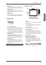
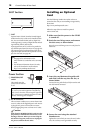
AD Output Section
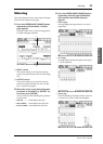
1 MONITOR OUT connectors L/R
These balanced TRS phone-type connectors output
monitoring signals or 2TR IN signals. The nominal
signal level is +4 dB.
You can select signals using the Monitor Source
selector.
2 OMNI OUT connectors 1–4
These balanced TRS phone-type connectors output
any Bus signals or channel Direct Out signals. The
nominal signal level is +4 dB.
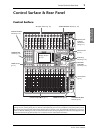
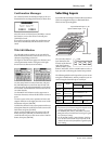
PHANTOM +48V (p. 16)
Power Section (p. 18)
AD Output Section
(p. 16)
SLOT Section (p. 18)
MIDI/USB Section
(p. 17)
Digital I/O Section
(p. 17)
Note:
• Make sure that this switch is turned off if phan-
tom power is not required.
• Before you turn on phantom power, make sure
that only devices requiring phantom power (such
as condenser mics) are connected. Supplying
phantom power to a device that does not require
it will cause malfunctions.
• Do not connect or disconnect a device while
phantom power is on. Doing so will damage the
device or the console.
• To protect your speakers, make sure that the
power amps (powered speakers) are off before
you turn phantom power on or off. We also rec-
ommend that all output level faders be mini-
mized. If you fail to observe these precautions,
high volume output may occur, possibly damag-
ing your hearing or your equipment.
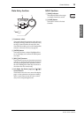
321
321
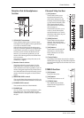
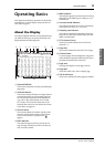
1/4" TRS phone plug
Ring
(cold)
Sleeve (ground)
Tip (hot)
1/4" TRS phone plug
Ring
(cold)
Sleeve (ground)
Tip (hot)