


Pairing Channels 33
01V96i—Owner’s Manual
Tutorial
Pairing Channels
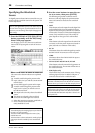
On the 01V96i, you can pair adjacent odd-even chan-
nels for stereo operation. Faders and most mix param-
eters of paired channels (excluding the Input Patch,
phase, routing, and pan parameters) are linked. Pairing
Input Channels is useful when you are connecting ste-
reo sources, such as a CD player or synthesizer.
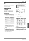
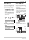
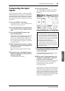
1. To pair adjacent odd-even Input Chan-
nels, press and hold the [SEL] button for
one of the channels you wish to pair, and
press the [SEL] button for the adjacent
channel.
The corresponding two channels are paired, and the
settings (such as faders, channel on/off, etc.) of the
first channel are copied to the second channel. Sub-
sequently, adjusting the linked parameters of one of
the paired channels will adjust the parameters of its
partner in the same way.
2. To cancel a pair, press and hold the [SEL]
button for one of the paired channels,
and press the [SEL] button for the other
channel.
Setting the Routing
To record the 01V96i input signals to an external
device, you must specify the destination of the signals
for each Input Channel. This process is called “routing.”
There are two routing methods.
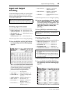
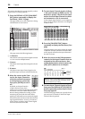
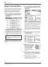
• Using Bus Outs 1–8
Input Channel signals are first routed to Buses 1–8,
then through Bus Outs 1–8 to the output connec-
tors or channels. Use this method if you want to mix
the signals of multiple Input Channels for output. If
you desire, you can process the signals using the Bus
Out 1–8 compressors and EQs.
In the following example, Input Channel signals are
routed through Bus Outs 1 and 2 to ADAT OUT
connectors 1 and 2.
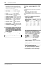
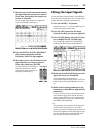
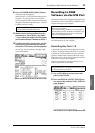
•Using Direct Outs
Each Input Channel signal is directly routed to and
output from the specified output connectors and
channels.
The following example illustrates the signals
directly output from ADAT OUT channels 1–5.
Tip: You can still select one of the paired channels for
control by pressing the corresponding [SEL] button.
When you select the channel, the [SEL] button indica-
tor lights up, and the [SEL] button for the paired part-
ner flashes.
Note: If you want to operate the faders of paired chan-
nels, make sure you operate only one fader for the pair.
If you try to operate the faders for both channels in the
pair, an excessive load will be applied to the fader
motor, causing malfunction.
Parameters are
copied.
SEL SEL SEL SEL SEL SEL
INPUT
connector 1
Input
Channels 1
CH 1
ADAT OUT
connector
Bus Out 1
INPUT
connector 2
Bus Out 2
INPUT
connector 3
Bus Out 3
INPUT
connector 4
Bus Out 4
INPUT
connector 5
Bus Out 5
CH 2
Input
Patch
Input
Channels 2
Input
Channels 3
Input
Channels 4
Input
Channels 4
INPUT
connector 1
Input
Channels 1
CH 1
ADAT OUT
connector
INPUT
connector 2
INPUT
connector 3
INPUT
connector 4
INPUT
connector 5
CH 2
Input
Patch
Input
Channels 2
Input
Channels 3
Input
Channels 4
Input
Channels 4
CH 3
CH 4
CH 5