2
Bosch Security Systems | 04-2003 | 3922 988 43318 en
Digital Congress Network | Installation and Operating Manual | Chapter 10 - Installation Techniques
en | 10-16
Remote Controller
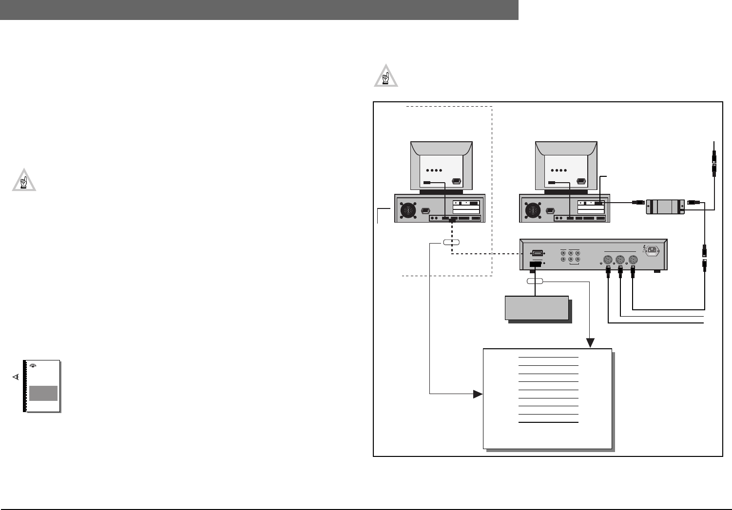
FIG 10-20 Multi-CCU configuration and connection
10.9 Remote Controller
The DCN system provides a facility for connecting to a ‘Remote controller. The remote controller
can be custom built to your requirements enabling remote control of the following functions”
• Microphone management
• Parliamentary voting
• Attendance registration
Dedicated control panels or control devices such as touch screens for example (available from
companies such as Creston and Panja) along with dedicated software interfaces can be used.
NOTE: Remote control is only available with the following CCU’s:
LBB 3500/15 and LBB 3500/35. The CCU uses its RS 232 serial COM-ports for remote
control. The communication between the CCU and the ‘Remote controller’ is message
based (remote functions and update notification). Messages are transported as binary
streams of bytes. (Refer to Software User Manual for Remote Control software LBB 3587).
The remote control interface must be configured by setting DIP-switches (S14) on the
Trunk Communication Board (TCB 4) See Chapter 4.7.
Requirements
1. The dedicated ‘Remote control’ software package LBB 3587/00 MUST BE installed on an
external (remote PC). This remote PC must be installed with the operating system DOS 5.0 or
higher and connected to the CCU using an RS232 cable (see Installation).
2. The DCN embedded software version MUST BE 7.00 or higher.
10.9.1 Installation
The ‘remote control’ interface software LBB 3587 can be installed in a ‘Single or a Multi CCU system.
During installation, options are available for changing the COM-port settings of the remote PC.
NOTE: For detailed functionality, installation, commands and communication
protocols refer to the user documentation delivered with the Remote control soft-
ware package LBB 3587/00. Extended information is available on request.
1. Single CCU System (LBB 3500/15 and LBB 3500/35 (FIG 10-21)
CCU types LBB 3500/15 and LBB 3500/35 have two RS232 serial ports (Port 1 and Port 2) located
at the rear of the unit. An RS-232 cable with 1 to 1 wiring (RS232 extension cable) is used to
connect the CCU to the remote controller. Note that these CCU’s uses hardware handshaking with
the CTS and RTS signals. All other ‘handshake’ signals are internally chained together in the CCU to
form the appropriate signals for the remote controller. The maximum cable length between the CCU
and the ‘Remote controller’ should not exceed 5 m (16.4 ft.). Where longer distances are required an
‘interface unit’ should be used to ensure correct transmission.
NOTE: The communication protocol and a higher baud-rate for the serial COM-port can
be adjusted as necessary (see Chapter 4.6 and Chapter 5.7).
FIG 10-21 Remote control Single CCU System
DCN
Software
Manuals
BOSCH
CD 1
Rx 2
Tx. 3
DTR 4
GND 5
DSR 6
RTS 7
CTS 8
RI 9
1. CD
2. Rx
3. Tx
4. DTR
5. GND
6. DSR
7. RTS
8. CTS
9. RI
Port 1
Port 2
Rec.
Line
In
Out
In
Out
Symmetrical
Trunk
115V-T4A 230V -T2A
Remote control
software LBB 3587
INSTALLED
OPEN INTERFACE
Remote PC
RS232
RS232
RS232
Remote
Controller
LBB 3500/15 or LBB 3500/35
LBB 4114/00
PC Network card
LBB 4115/00
DCN Control PC
SINGLE CCU SYSTEM
Male Female


