2
Bosch Security Systems | 04-2003 | 3922 988 43318 en
Digital Congress Network | Installation and Operating Manual | Chapter 4 - Central Control Equipment
en | 4-12
CCU Audio Routing Modes
4.9 CCU Audio Routing Modes
To provide additional functionality in the CCU, the DCN software from release version 7.01 includes
two new ‘Audio Routing’ modes - ‘MIX-MINUS’ and ‘INSERTION’ mode. Both modes are selected by
setting DIP-switches (S9) on the TCB4 card located in the Central Control Unit CCU (see Chapter
4.5.2).
MIX-MINUS mode (FIG 4-8)
The main feature of this mode, is that audio signals connected to the ‘Line-Input’ of the CCU are no
longer routed to the ‘Line-Output’ of the CCU. This feature is especially desired for the following
applications:
1. Where a remote audio connection is made via a telephone coupler for connection to a remote
delegate or specialist speaker.
2. To interconnect two DCN systems.
IMPORTANT!: In the ‘Mix Minus’ mode, a permanent audio channel is used for ‘Line-Input’.
Therefore the number of available interpretation channels is one channel less than in the standard
mode (i.e. 10 channels instead of 11 channels as available in ‘Stand-alone’ and ‘Multi-CCU’ systems.
NOTE: For recording the total audio signal (i.e. Floor + Line-Input) use an Audio Media
Interface unit LBB 3508/00 on channel 0 (see Chapter 4.11).
Using this mode of operation, the audio connection is considerably improved, and avoids ‘Echo’ due
to feedback as was experienced in the standard mode of operation.
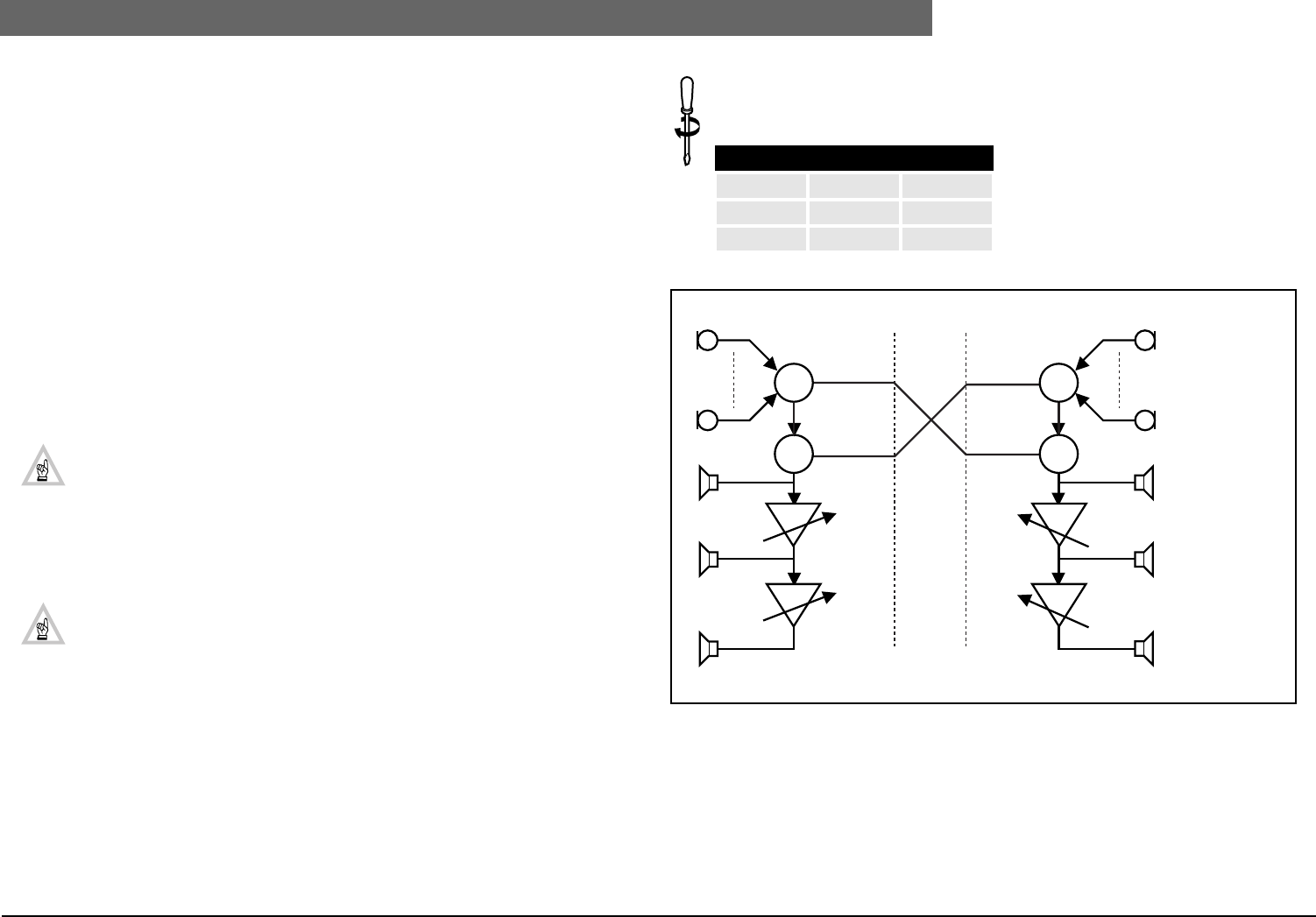
FIG 4-8 gives an example of ‘Audio Routing’ in the CCU’s and the external routing for connection of
two DCN systems A and B.
NOTE: If connection is done via the Public Telephone Network, telephone couplers must
be used (not shown in FIG 4-8).
Installation:
To set the CCU for the Mix-Minus mode Dip-switch ‘S9’ on the Trunk
Communication Board must be set as follows:
FIG 4-8 ‘MIX-MINUS’ mode
DIP-switch S9
Switch-2 Switch-3 Mode
Off Off Standard
On Off Mix-Minus
∑
∑
∑
∑
DCN System A
CH.13
CH.12
CH.0
CH.14 CH.14
CH.13
CH.12
CH.0
CCU Volume
Line-OUT Line-OUT
Line-IN Line-IN
CCU Volume
DCN System B
Mix-Minus
Insertion OUT
Mix-Minus
Insertion IN
Mix-Minus
Insertion IN
Mix-Minus
Insertion IN
Master volume
PC control
Master volume
PC control
Delegate/Chairman
microphones
Interpreter headphones
Unit loudspeaker
Delegate headphones
Equalizer PA
Local PA (MCCU)
Delegate unit
loudspeaker
(See Chapter 4.5.2 (Table 4-4:)


