2
Bosch Security Systems | 04-2003 | 3922 988 43318 en
Digital Congress Network | Installation and Operating Manual | Chapter 6 - DCN Camera Control
en | 6-4
Allegiant Video Switcher
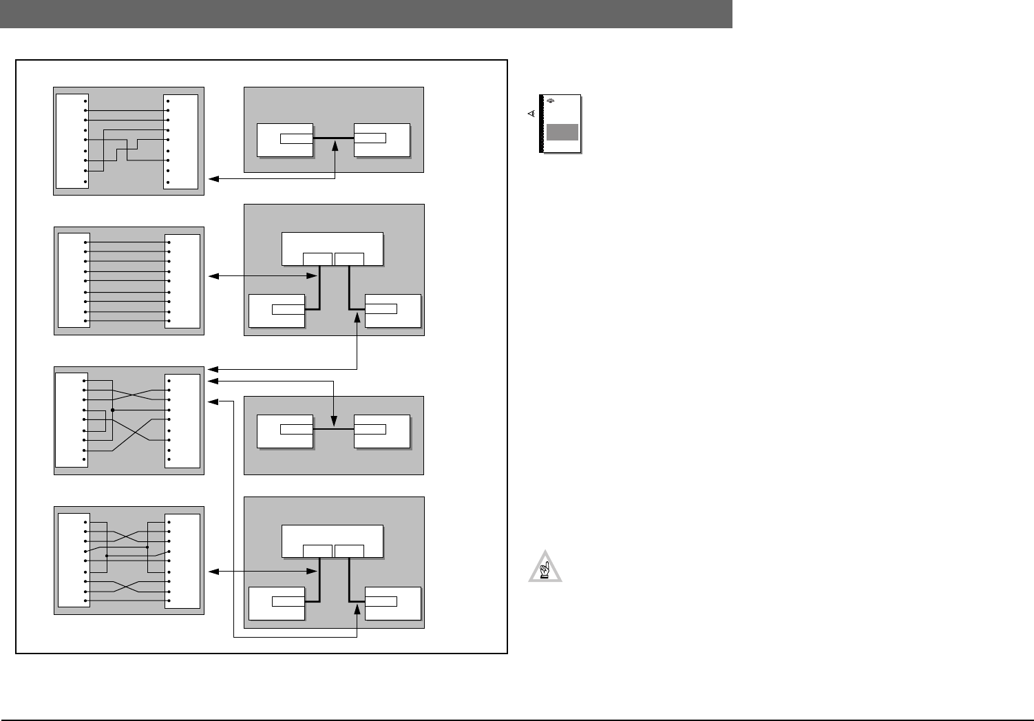
FIG 6-3 RS232 Connections for AVS
6.1.4 Set-up Camera configuration
Reference: To configure and set-up camera positions according to delegate/chairman
microphone activity, DACC is available for Stand-alone DCN systems using DCN
software package LBB 3562/00 and LBB 3588/00 for PC controlled systems. Refer to
the relevant software manuals when programming the
configuration for the DACC system.
To Install and download the required software modules proceed as follows:
6.1.4.1 Stand-alone DCN System with Camera Control
For camera installation with stand-alone Camera Control software LBB 3562/00 a temporary PC
connection is required. The minimum PC requirements are as follows:
• 80486 DX/66 MHz or Pentium processor
• Operating system: Windows 95, Windows 98, Windows 2000, Window NT 4.0
• 4MB Random Access Memory (RAM)
• Video card: SVGA resolution 640 x 480 pixels, 256 colours
• Floppy disc drive 3.5 inch, 1.44 MB
• 100 MB hard disk
• 2 Serial ports
• Monitor or built-in colour LC-display
• Keyboard and mouse
6.1.4.2 Installation of a Single CCU
1. Connect the temporary PC (COM-port 2) to the Allegiant Video switcher (console port).
2. Connect the temporary PC (COM-port 1) to the CCU (Port 2) (see FIG 6-3 (2)).
6.1.4.3 Installation of a Multi-CCU
1. Connect the temporary PC (COM-port 2) to the Allegiant Video switcher (console port).
2. Connect the temporary PC CCU (COM-port 1) to the Master CCU (COM-port 2)
(see FIG 6-3 (4)).
NOTE: The PC must be installed with the following:
1. OS/2 operating system
2. Multi-CCU interface card LBB 3511/00
3. Multi-CCU software LBB 3586/00
6.1.4.4 4. PC COM Port settings
COM 1 for communication to the CCU (default)
COM 2 for communication to the video switcher
If other settings are required they must be specified in the DCNCI.INI file in the Windows directory.
The following settings must then be added or changed depending on the selected COM-port:
1
2
3
*1
4
(Male)
(Female)(Wire - to - Wire cable)
(Cable LTC 8506/00)
CCU
PC
1
2
3
4
5
6
7
8
9
DCD
RD
TD
DTR
GND
DSR
RTS
CTS
RI
1
2
3
4
5
6
7
8
9
DCD
RD
TD
DTR
GND
DSR
RTS
CTS
RI
9 pole D-type
(Male)(Female)
9 pole D-type
PC
Video Switcher
CCU
(Male)
(Male)
1
2
3
4
5
6
7
8
9
GND
RD
TD
CTS
RTS
n.c
GND
n.c
n.c
1
2
3
4
5
6
7
8
9
DCD
RD
TD
DTR
GND
DSR
RTS
CTS
RI
9 pole D-type
Video Switcher
DCD
RD
TD
DTR
GND
DSR
RTS
CTS
RI
1
2
3
4
5
6
7
8
9
1
2
3
4
5
6
7
8
9
GND
RD
TD
CTS
RTS
n.c
GND
n.c
n.c
(Female)
(Female)(Null Modem Cable)
OS2/CCU
PC
1
2
3
4
5
6
7
8
9
DCD
RD
TD
DTR
GND
DSR
RTS
CTS
RI
1
2
3
4
5
6
7
8
9
DCD
RD
TD
DTR
GND
DSR
RTS
CTS
RI
9 pole D-type
RS232 RS232
Single CCU
(female) (female)
Video Switcher
RS232 RS232
OS/2 Master CCU
COM 2
PC
(female)
Video Switcher
RS232
COM1
COM2
RS232
Single CCU
(female) (female)
Video Switcher
Temporary Installation PC
Connection Installation PC
to CCU and Video Switcher
Single CCU to Video Switcher
Connection OS/2 Master CCU
to Video Swicher
RS232
COM1
COM2
RS232
(male)
(male)
(female)
Video Switcher
Temporary Installation PC
Connection Installation PC
to OS/2 Master CCU and Video Switcher
OS/2 Master CCU
COM 2
PC
DCN
Software
Manuals
BOSCH


