


64
Sound operating mode
Filter: Filter Type
At (Attack Level Swing)
This parameter specifies the direction of change in “Attack
Level” caused by “AMS1/2”. If “Intensity” is a positive (+) value, a
setting of + will raise the EG level, and a setting of – will decrease
it. With a setting of 0 there will be no change.
Time Modulation
AMS (Alternate Modulation Source)
This parameter selects the source that will control the “Time”
parameters of the pitch EG (see “AMS (Alternate Modulation
Source) list” on page 77).
Intensity (AMS Intensity)
This parameter specifies the depth and direction of the effect
that “AMS” will have on the “Time” parameters. With a setting of
0, the pitch EG times will be just as specified by the “Time” set-
tings.
The alternate modulation value at the moment that the EG
reaches each point will determine the actual value of the EG time
that comes next.
For example, the decay time will be determined by the alternate
modulation value at the moment that the attack level is reached.
When this parameter is set to values of 16, 33, 49, 66, 82, or 99,
the specified EG times will speed up as much as 2, 4, 8, 16, 32, or
64 times respectively (or slowed down to 1/2, 1/4, 1/8, 1/16, 1/32,
or 1/64 of the original time).
For example if “AMS” is set to Velocity, increasing the absolute
value of “Intensity” will allow strongly-played notes to increase
the changes in pitch EG “Time” values. The direction of the
change is specified by “At (Attack Time Swing)” and “Dc (Decay
Time Swing)”. As you play more softly, the pitch EG times will
more closely approach the actual settings of the pitch EG.
-99…+99 Parameter value.
At (Attack Time Swing)
This parameter specifies the direction in which “AMS” will affect
the “Attack Time” parameter. With positive (+) values of “Inten-
sity”, a setting of + will cause the time to be lengthened, and a
setting of – will cause the time to be shortened. With a setting of
0 there will be no change.
Dc (Decay Time Swing)
Specify the direction in which “AMS” will affect the “Decay
Time”. With positive (+) values of “Intensity”, a setting of + will
cause the time to be lengthened, and a setting of – will cause the
time to be shortened. With a setting of 0 there will be no change.
Filter: Filter Type
Here you can make settings for the filters that will be used by the
oscillators. You can select either a 24 dB/octave low pass filter
with resonance, or a series connection of a 12 dB/octave low pass
filter and a 12 dB/octave high pass filter.
Filter Type
This parameter selects the type of filter (Low Pass Resonant, Low
Pass & High Pass) for the selected oscillator.
Low Pass Resonance
When the Low Pass filter type is selected, only fil-
ter A will be activated.
Low Pass & High Pass
When the Low Pass & High Pass filter type is
selected, the filter B will be activated.
Trim
Use this parameter to adjust the level at which the audio signal
output from the selected oscillator is input to filter A.
Note: If this value is raised, the sound may distort if Resonance is
set to a high value or when you play a chord.
00…99 Trim level.
Filter A
Frequency (Cutoff Frequency A)
This parameter specifies the cutoff frequency of filter A.
00…99 Cutoff frequency value.
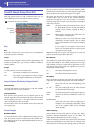
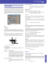
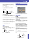
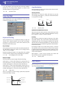
Pitch EG changes (Time) (AMS = Velocity, Intensity = positive (+) value)
Note-on
Note-off
Note-on
Note-off
Note-on
Note-off
A note played softly with
Attack Time Swing set to +
and Decay Time Swing set to
A note played strongly with
Attack Time Swing set to + and
Decay Time Swing set to +
A note played strongly with
Attack Time Swing set to – and
Decay Time Swing set to –
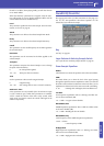
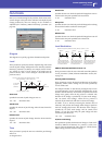
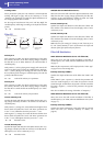
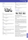
Frequency
Level
Low Pass
12dB/oct
24dB/oct
This is a filter that cuts the
high-frequency region above the cutoff
frequency.
This is the most common type of filter,
and is used to cut part of the overtone
components, making an originally bright
timbre sound more mellow (darker).
When the “Filter Type” is Low Pass
Resonance, the cutoff will have a
steeper slope.