


67
Sound operating mode
Filter: Filter LFO
Advanced
Filter: Filter LFO
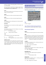
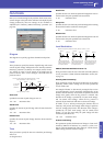
Here you can use the filter LFO to apply cyclic modulation to the
cutoff frequency of the filter (for the selected oscillator) to create
cyclical changes in tone.
LFO 1
Intensity to A
Specifies the depth and direction of the modulation that LFO1
(set on “LFO: LFO1”) will have on the cutoff frequency of filter
A. Negative (–) settings will invert the phase.
-99…+99 Parameter value.
Intensity to B
Specify the depth and direction of the modulation that LFO1
will have on the cutoff frequency of filter B (see “Intensity to A”).
-99…+99 Parameter value.
JS (Joystick) –Y Intensity to A
By moving the joystick in the Y direction (toward yourself), you
can control the depth at which LFO1 modulates the cutoff fre-
quency of filter A. This parameter specifies the depth and direc-
tion of the control.
Higher settings of this parameter will produce greater increases
in the effect of LFO1 on the filter when the joystick is moved
toward yourself.
-99…+99 Parameter value.
JS (Joystick) –Y Intensity to B
By moving the joystick in the Y direction (toward yourself), you
can control the depth at which LFO1 modulates the cutoff fre-
quency of filter B. This parameter specifies the depth and direc-
tion of the control (see “JS (Joystick) –Y Intensity to A”).
AMS (Filter LFO1 Alternate Modulation Source)
Select a source that will control the depth and direction of cutoff
frequency change for both filters A and B. See “AMS (Alternate
Modulation Source) list”.
Intensity to A
Specifies the depth and direction of the effect that “AMS” will
have on filter A.
For example if “AMS” is After Touch, higher settings of this
parameter will allow greater change to be applied to LFO1 when
you apply pressure to the keyboard.
-99…+99 Parameter value.
Intensity to B
Specifies the depth and direction of the effect that “AMS” will
have on filter B (see “Intensity to A”).
LFO 2
Adjusts the depth of the cyclic modulation applied by LFO2 (set
on “LFO: LFO2”) to the cutoff frequency of filters A and B. For
more information on the parameters see “LFO 1” above.
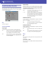
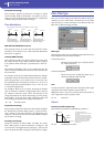
Filter: Filter EG
Here you can make settings for the EG that will produce time-
varying changes in the cutoff frequency of filters A and B for the
selected oscillator. The depth of the effect that these settings will
have on the filter cutoff frequency is determined by the “Veloc-
ity” and “Intensity” parameters.
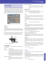
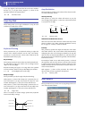
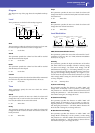
Diagram
The diagram on top of the page shows the Filter envelope line.
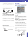
Filter envelope
Level
These are the envelope segment levels. The result will depend on
the filter that was selected in “Filter Type”. For example, with the
Low Pass Resonance filter, positive (+) values of EG Intensity
will cause the tone to be brightened by positive (+) levels, and
darkened by negative (–) levels.
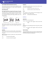
Change in cutoff
Low setting High setting
Note-on
Note-off
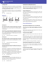
Attack
Time
Start
Level
Decay
Time
Release
Time
Release
Level
Attack Level
The specified
cutoff
frequency
Sustain Level
Time
Break
Point
Level
Slope
Time