


67
Chapter 1 Creating Your Own Drum Kit (Kit Edit)
1
the instrument (the drum kit part) or the percussion set
instrument (the percussion part) is to be played when the note
number is received (SETUP/MIDI COMMON/CH10Priorty;
p. 99).
When Setting Multiple Pads to the Same Note
Number
When using an external MIDI device to play TD-6 drum kits,
if overlapping note numbers are received, the instrument
assigned to the pad connected to the lowest-numbered trigger
input is sounded.
When note numbers for the head and rim are duplicated, the
head instrument is played.
When the pad is struck, the note number set for the pad is
sent.
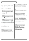
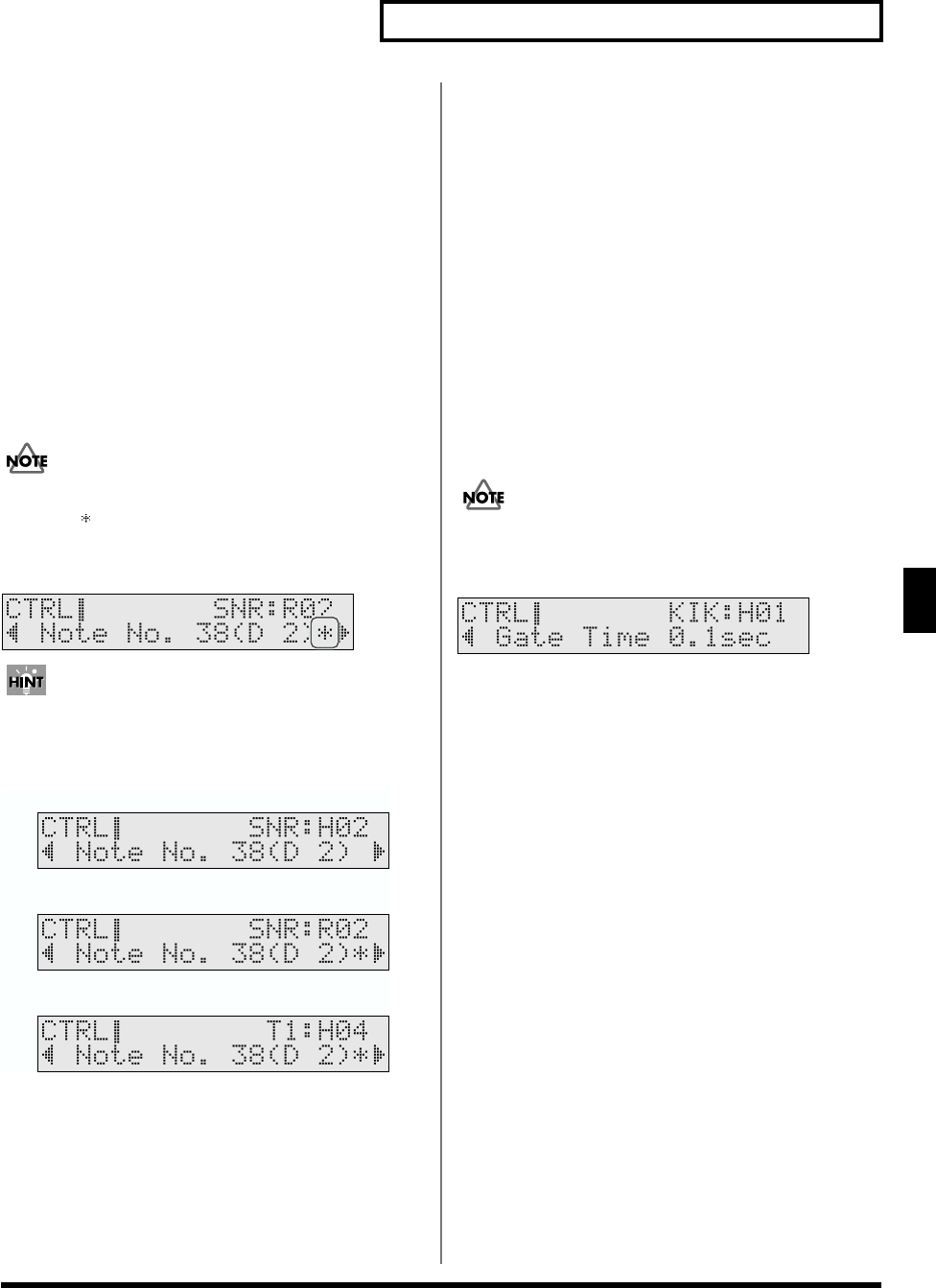
When the same note number is assigned to more than one
pad, then “ ” appears in the settings screen for the pad that
is prevented from sounding even when the Note Number is
received.
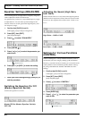
fig.01-040ai
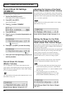
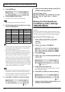
The following appears in the display when “38 (D2)” is
specified for the head (H02) and rim (R02) of Trigger Input 2
(SNARE) and the head (H04) of Trigger Input 4 (TOM1).
fig.01-042ai.e
In this case, when Note Number 38 (D2) is received, the
instrument assigned to the HEAD of TRIGGER INPUT 2
(SNARE) is played.
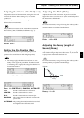
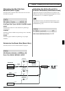
MIDI Gate Time for Each Pad
(Gate Time)
For each pad, you can specify the length of time the note will
“hold” during transmission from the MIDI OUT.
Percussion sound modules normally produce sound only in
response to “Note on” messages, and ignore “Note off”
messages. However general-purpose sound modules or
samplers do receive the note-off messages that are transmitted
and respond by turning off the sound.
At the factory settings, the Gate Time setting is set to the
minimum value, since a drum sound module will likely not
make use of it. If a sound module received this data as it is
receiving a Note OFF message, the interval will be too short,
so most sounds will not be played (or it may sound like barely
perceptible noise). To avoid this problem, set a longer gate
time for each pad that is to be played.
This setting cannot be made in GM mode (p. 100).
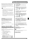
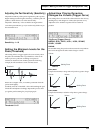
fig.01-045_50
Gate Time: 0.1–8.0 sec (0.1 sec. steps)
Tr igger Input 2 (SNARE) Head
Tr igger Input 2 (SNARE) Rim
Tr igger Input 4 (TOM1) Head