


Getting Started
2
80E00 Electrical Sampling Modules User Manual
Product Description
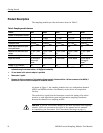
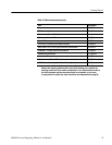
The sampling modules provide the features shown in Table 2.
Table 2: Sampling module features
Feature 80E01 80E02 80E03 80E04 80E06
Number of independent channels 1 2 2 2 1
Rise time 7 ps, typical
1
≤28 ps ≤17.5 ps ≤17.5 ps ≤5.0 ps, typical
1
Bandwidth 50 GHz 12.5 GHz 20 GHz 20 GHz 70 GHz, typical
Displayed noise
3
≤2.3 mV
RMS
≤800 V
RMS
≤1.2 mV
RMS
≤1.2 mV
RMS
≤2.8 mV
RMS
Select channel buttons for quick
trace identificat ion
Yes Yes Yes Yes Yes
Maximum non-destruct ive input
voltage
2 V (DC + peak
AC)
3 V (DC + peak
AC)
3 V (DC + peak
AC)
3 V (DC + peak
AC)
2 V (DC + peak
AC)
Vertical sensitivity, full scale 10mVto1V 10mVto1V 10mVto1V 10mVto1V 10mVto1V
Signal connectors
2
2.4 mm male to
2.92 mm (K)
female
3.5 mm female 3.5 mm female 3.5 mm female 2.4 mm male to
2.92 mm (K)
female
4
Number of TDR channels N.A. N.A. N.A. 2 N.A.
1
The 80E01 module risetime is estimated using the formula risetime = 0.35/bandwidth. The 80E06 module risetime is
estimated using the formula risetime = 0.35/(typical bandwidth).
2
3.5 m m female to 2.4 mm male adapter is provided.
3
Measured at 1 ps/div.
4
Because the 2.4 mm connector of this adapter will mechanically interface with the 1.85 mm connector of the 80E06, it
serves as a 1.85 mm-to-2.92 mm adapter for the 80E06 module.
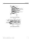
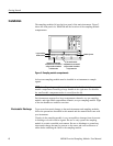
As shown in Figure 1, the sampling modules have two independent channels
(80E01 and 80E06 each have one channel), each with its own acquisition
circuitry.
The strobe drive signal from the instrument controls the timing of the strobe
assertion to each acquisition system and guarantees sampling coincidence
between the channels in a sampling module.
CAUTION. To prevent electrostatic damage to the main instrument and sampling
modules, follow the precautions described in this manual and the manuals
accompanying your instrument. (See Electrostatic Discharge on page 6.)