


Reference
20
80E00 Electrical Sampling Modules User Manual
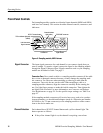
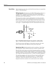
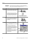
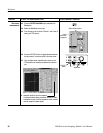
When the diode switch opens (reverse-biased), apparent resistance to ground at
the acquisition point (and at the channel connector) is 25 Ω because the internal
termination resistance is 50 Ω in parallel with the connector impedance of 50 Ω.
The voltage at the acquisition point rises to +250 mV.
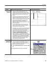
The transition propagates to the open in the DUT and is positively reflected back
to the acquisition point, causing the voltage at the acquisition point to rise to
+500 mV. At the acquisition point, the time displayed from the first step to the
second step is the round trip propagation time from the acquisition point to the
open in the DUT and back. See Figure 10.
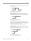
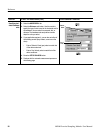
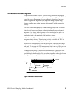
Baseline Correction. The baseline of a current-source based step generator
normally shifts its DC level with loading. The use of a DC current source to
cancel the step source current maintains the baseline level close to 0 V (see
Figure 7 on page 18).
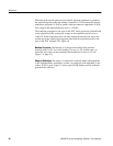
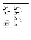
Shape of Ref lections. The shape of a reflection reveals the nature and magnitude
of the load impedance, mismatch, or fault, even when the load impedance is not
a short, 50 Ω, or open. Figure 11 shows typical TDR displays and the load that
generated the reflection.