


Reference
34
80E00 Electrical Sampling Modules User Manual
Overview Control elements & resources
To take a comm on mode or differential TDR
measurement (cont.)
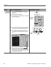
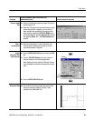
Preset TDR 4. Initialize the instrument (press DEFAULT SETUP).
5. Press the SETUP DIALOGS button and select the TDR
tab.
6. Press TDR Preset for both channels (for the sampling
module connected to the cables) to turn them on. Select
the polarity desired for both channels.
TDR Preset sets Internal Clock in the Trigger menu,
turns on the TDR Step in the TDR Setups menu, turns
on and selects the acquisition Units in the TDR Setups
menu.
The sampling module will turn on red lights next to the
SELECT CHANNEL buttons, indicating that TDR is
activated for the channels.
7. Set the scale to ρ.
8. Press the SETUP DIALOGS button to dismiss the
dialog box.
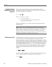
TDR tab
Set
units
Enable
TDR
TDR
preset
Set Other TDR
parameters
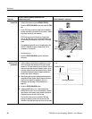
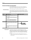
9. Adjust the Manual Step Deskew adjustment to set the
time at which the step generator for the right channel
asserts the TDR step relative to the left channel. Notice
that the second edge moves horizontally, relative to the
first edge. Adjust the right step generator step to divide
the mism atch between channels equally between the
incident step and the reflections.
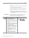
10. After dividing the mismatch equally between channels
using M anual Step Deskew, adjust Channel Deskew to
align the front edge of the reflections. (for more
information see Adjusting TDR Step Deskew on
page 37).
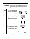
11. Press the SETUP DIALOGS button.
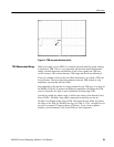
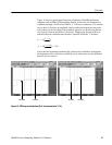
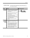
12. Adjust the VERTICAL (2.5 ρ in this example) and
HORIZONTAL SCALE (2 ns in this example) to show a
trace similar to t hat shown. Leave at least one division
of basel ine t race to the left of the first rise.
The fi rst rise of this trace is the incident TDR step
leaving the sampling module; the second rise is the
reflect ion of the step returning from the end of the cable.
ρ
ρ
Front edge of reflections
Incident TDR steps