


Reference
80E00 Electrical Sampling Modules User Manual
33
Read the following topics; they provide details that can help set up to take
effective differential and common mode TDR measurements.
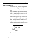
The 80E04 TDR/sampling module is able to perform differential and common-
mode TDR measurements. As described earlier, the sampling module has two
input channels and two independent step generators.
The step-generator output for each channel is selectable for positive or negative
polarity and amplitude. This section will show you how to use the two channels
and step generators of the 80E04 to perform differential and common-mode TDR
measurements.
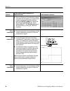
This example demonstrates the common-mode and differential TDR features of
the 80E04 sampling module.
Overview
To take a comm on mode or differential TDR
measurement
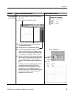
Control elements & resources
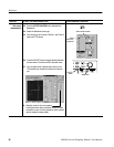
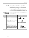
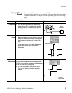
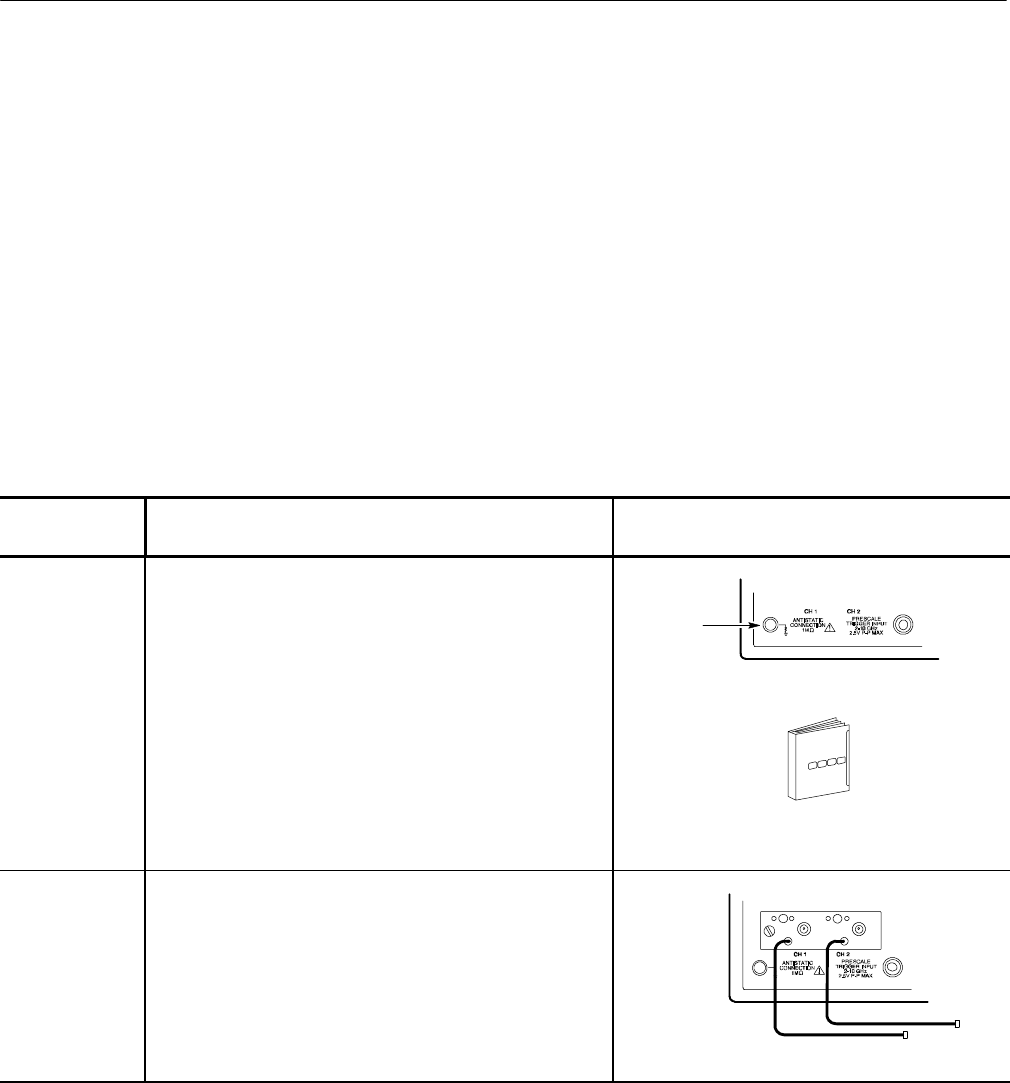
Prerequisites 1. Connect your wrist strap to the antistati c connector on
the f ront of your instrument.
Connect
wrist strap
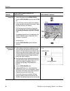
2. An 80E04 sampling module must be installed in a DSA
digital analyzer, a TDS oscilloscope , or a CSA analyzer.
The acquisi tion system should be set to Run.
See the main instrument user documentation and
online help for scaling and acquisition setup
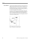
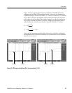
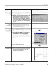
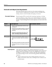
Input 3. Connect transmission lines to the sampling module
using proper probing/connecting techniques for your
application (f or exam ple: two SMA cables, preferably of
matched length). Connect the device under test to the
transmission lines (Connect the conductors of a
differential line to the center conductors. Connect the
shields together).
Keys to Using
To Take a Common-Mode
or Differential TDR
Measurement