


Reference
18
80E00 Electrical Sampling Modules User Manual
Read the following topics; they provide details that can help you set up and take
effective TDR measurements.
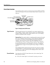
TDR Step Generat ion. Both channels in the 80E04 TDR/sampling module have a
selectable polarity step generator which gives both channels measurement
capabilities. You can use the outputs of both generators to perform differential
and common-mode TDR measurements.
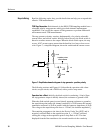
The step generator circuitry consists, fundamentally, of a polarity-selectable
current source and a diode switch. Initially, before the step, the diode switch is
biased to conduct current to the output. When the diode switch opens, the step
occurs. A DC current source assures that the baseline level stays close to zero
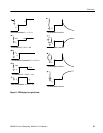
volts. Figure 7, a simplified diagram, shows the switch and the current source.
Acquisition point to
main instrument
50 Ω
10 mA
DUT
10 mA
Figure 7: Simplified schematic diagram of step generator - positive polarity
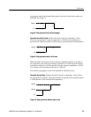
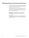
The following sections and Figures 8--10 describe the operation with a short
circuit, an open circuit, and a 50 Ω load, with a positive step source.
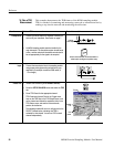
Operation Into a Short. Initially, the diode switch is conducting --10 mA. Since
the step-generator output is initially shorted, the resistance to ground is 0 Ω.
When the diode switch opens (reverse-biased), apparent resistance to ground at
the acquisition point (and at the channel connector) is 25 Ω because the internal
termination resistance is 50 Ω in parallel with the connector impedance of 50 Ω.
The voltage at the acquisition point rises to +250 mV, the incident amplitude E
i
.
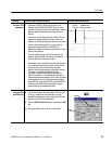
The transition propagates to the short in the Device Under Test (DUT) and is
negatively reflected back to the acquisition point, E
r
= --250 mV reflected,
causing the voltage at the acquisition point to drop back to 0 V. The time
displayed from the first transition to the second transition is the round trip
Keys to Using