


Operating Basics
80E00 Electrical Sampling Modules User Manual
13
H If you press the button and the channel is not currently acquiring (for any
channel or math waveform), then the instrument activates (turns on) the
channel.
H If you press the button and the channel is currently active as a channel
waveform, then the instrument selects the channel waveform.
H If the channel waveform is already selected when you press the channel
button, the instrument turns the channel off.
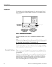
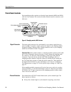
The TEKPROBE connector provides support for accessories requiring
TEKPROBE SMA support at levels 1 and 2. The connector provides power and
control to attached accessories, by the main instrument.
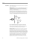
On modules with TDR capability, the red TDR ON light indicates whether the
step generator is sending out a step through the signal connector. The main
instrument turns this on or off.
System Interaction
Your sampling module is a part of a larger instrument system. Most of the
sampling-module functions, such as vertical and horizontal scale, are controlled
automatically by the main instrument. You do not directly control these
parameters; they are controlled for you as you perform tasks on the main
instrument. The parameters that you control from the sampling module front
panel are covered in Front-Panel Controls on page 12.
You also control external channel attenuation from the main instrument. External
Attenuation enables you to enter a number representing external attenuation you
have added to a channel.
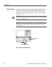
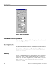
Commands From the Main Instrument Front Panel
The Vertical Setup dialog box accesses the sampling module controls. This
dialog box is shown in Figure 6.
You first select the channel in the Waveform section of the dialog box. Then you
select the Setup Scale, Position, Channel Offset, Deskew, Units, or External
Attenuation boxes to change those settings.
Detailed information on this dialog box can be found in the online help accessed
from the main instrument.
TEKPROBE Connector
TDR On Indicator