


Reference
80E00 Electrical Sampling Modules User Manual
27
TDR Measurements Background
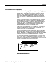
TDR is based on a simple concept: Whenever energy transmitted through any
medium encounters a change in impedance, some of the energy is reflected back
toward the source. The amount of energy reflected is a function of the trans-
mitted energy and the magnitude of the impedance change. The time lapse
between energy transmission and the reflection returning is a function of the
distance from the source to the impedance discontinuity, and the propagation
velocity.
The effects of this phenomenon are evidenced through echoes that occur when
sound encounters a wall. In electrical systems, a similar phenomenon occurs
when electrical energy traveling in a transmission line encounters a change in
impedance. Any change in the impedance of the transmission line, such as a
variation in the width of a circuit board trace, causes a reflection with an
amplitude related to the magnitude of the impedance change.
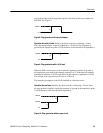
A Time Domain Reflectometer sends out a step on the cable, circuit board, or
integrated circuit under test. The reflection (or echo) received by the TDR is
measured to find events along the path of the step.
Reflections are caused both by events that are expected, such as width changes
and components, and by those that shouldn’t be there, such as bridges, shorts,
and opens. The strength of a TDR measurement is that it not only tells you there
is a fault, but it also tells you the magnitude and the distance to that fault.
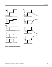
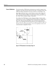
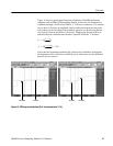
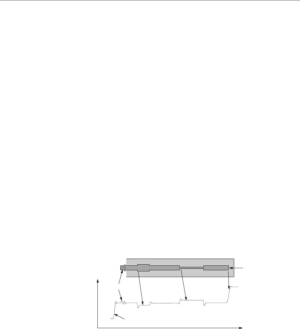
TDR can note any change in the characteristic impedance of the device-under-
test (DUT). Any change in the impedance is shown on the TDR display as an
upward bump or downward dip in the waveform, depending on the type of event
(see F igure 12 for example discontinuities in a microstrip).
Connector
Round trip time
Open
circuit
Volts or ρ
Incident step
Capacitive
discontinuity
Inductive
discontinuity
Conductor
Figure 12: Microstr ip discontinuities