


Operating Basics
12
80E00 Electrical Sampling Modules User Manual
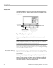
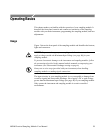
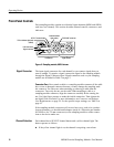
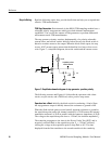
Front-Panel Controls
Each sampling module contains two identical input channels (80E01 and 80E06
each have one channel). This section describes channel controls, connectors, and
indicators.
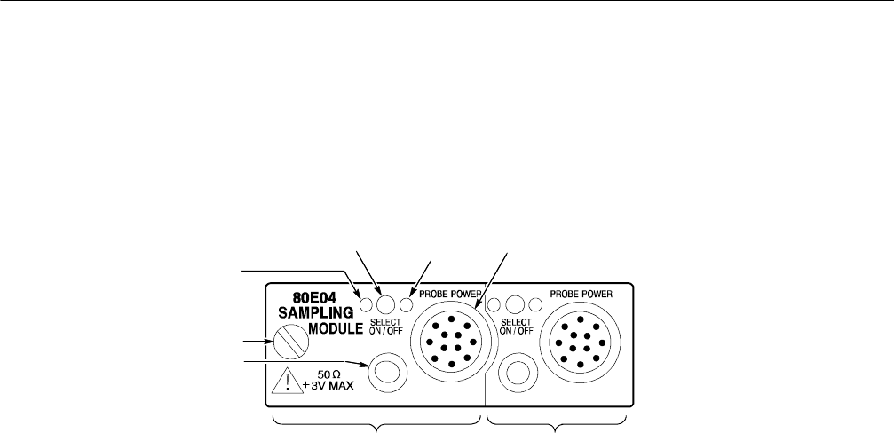
TDR on indicator light (red)
(80E04)
Signal connector
Left channel
Right channel
Hold-down screw
SELECT channel button TEKPROBE connector
Channel indicator
light (yellow)
Figure 5: Sam pling module, 80E04 shown
The input signal connectors for each channel let you connect signals that you
want to sample. To acquire a signal, connect the signal to the sampling module
through the Signal Connector input. Signal connectors used on your sampling
module are described in Table 2 on page 2.
Connector Care. Never attach a cable to a sampling-module connector if the cable
has a worn or damaged connector because you may damage the sampling-mod-
ule connector. Use extra care when attaching or removing a cable from the
connectors. Turn only the nut, not the cable. When attaching a cable to a
sampling-module connector, align the connectors carefully before turning the
nut. Use light finger pressure to make this initial connection. Then tighten the
nut lightly with a wrench. For more information, see Connector and Adapter
Care Requirements on page 38. For the specific torque settings, see Table 5 on
page 42.
If the sampling-module connectors will receive heavy use, such as in a produc-
tion environment, you should install adapters (such as a Tektronix part number
015-0549-xx for 3.5 mm connectors) on the sampling module to make connec-
tions to the device under test.
Each channel has a SELECT channel button and a yellow channel light. The
button operates as follows:
H If the yellow channel light is on, the channel is acquiring a waveform.
Signal Connector
Channel Selection