


Reference
32
80E00 Electrical Sampling Modules User Manual
A number of issues must be considered to make accurate TDR measurements. In
general it is relatively easy to make impedance measurements near the reference
impedance (usually 50 Ω). Higher accuracy or measurements farther from the
reference impedance requires more care. The following list covers a few key
considerations in making accurate and repeatable impedance measurements.
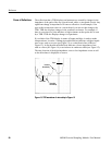
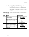
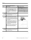
Resolution. Resolution determines the shortest impedance discontinuity that a
TDR instrument can measure. Because of round trip effects, Resolution =
1/2(System Reflected Rise Time). If a discontinuity, such as a variation in the
width of a trace, is small with respect to the system rise time, the reflection will
not accurately represent the impedance of the discontinuity. In extreme cases, the
discontinuity may effectively disappear. System rise time is the combined rise
time of the step generator (TDR), the instrument, and the interconnect between
the TDR and the circuit under test. In general, the most significant limitation in
impedance testing is the probe. Close attention to probe geometry and probing
techniques can greatly enhance resolution.
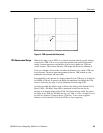
Reference Impedance. All TDR measurements are relative; they compare an
unknown impedance to a known impedance. The accuracy of the results depends
directly on the accuracy of the reference impedance. Any error in the reference
impedance translates to error in the measured impedance. It is also a good idea to
use a reference impedance close to the expected measured impedance because a
smaller difference between the reference and unknown impedance reduces
uncertainty in the measurement.
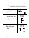
Cable Losses. Always use the shortest high-quality cable possible to connect to
the test fixture. The cable that connects the TDR unit to the circuit board not
only degrades the system rise time, but can cause other aberrations in the system
response that add to measurement error.
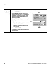
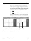
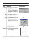
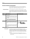
Taking Differential and Common-Mode TDR Measurements
This section describes how to use the 80E04 to take differential and common-
mode time-domain reflectometry (TDR) measurements.
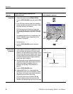
To take TDR measurements on coupled transmission lines. Using common-mode
and differential TDR, you can characterize coupled transmission lines.
The Tektronix 80E04 sampling module is a true differential sampling module for
more accurate differential TDR measurements.
This feature only works with an 80E04 sampling module.
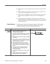
Making A ccurate TDR
Measurements
Why Use?
What’s Special?
What’s Excluded?