


Table of Contents
ii
80E00 Electrical Sampling Modules User Manual
List of Figures
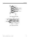
Figure 1: Samplin g module block diagram 3.....................
Figure 2: Samplin g module, 80E04 shown 3.....................
Figure 3: Sampling module compartments 6.....................
Figure 4: Installing a sampling module 8........................
Figure 5: Samplin g module, 80E04 shown 12.....................
Figure 6: Vertical Setup dialog box 14...........................
Figure 7: Simplified schematic diagram of step
generator - positive polarity 18..............................
Figure 8: Step generator with a shorted output 19.................
Figure 9: Step generation with a 50 Ω load 19.....................
Figure 10: Step generation with an open circuit 19.................
Figure 11: TDR displays for typical loads 21......................
Figure 12: Microstrip discontinuities 27..........................
Figure 13: TDR waveform of microstrip in Figure 12 28............
Figure 14: TDR step and reflection (short) 29.....................
Figure 15: TDR step and reflection
(50 Ω line terminated in 75 Ω)31............................
Figure 16: TDR step of undamaged sampling module 44............
Figure 17: First example of EOS error 45........................
Figure 18: Second example of EOS error sh owing
cumulative effect 46.......................................
List of Tables
Table 1: Application software version required 1.................
Table 2: Sampling module features 2...........................
Table 3: Standard accessories 4...............................
Table 4: Optional accessories 4................................
Table 5: Torque Wrench Information 42.........................
Table 6: Electrical sampling modules -- Descriptions 47............
Table 7: Electrical sampling modules -- Signal acquisition 48.......
Table 8: Electrical sampling module (80E04) -- TDR system 50......
Table 9: Electrical sampling modules -- Timebase system 51........
Table 10: Electrical sampling modules -- Power consumption 51.....
Table 11: Electrical sampling modules -- Mechanical 52............