Specifications
80E00 Electrical Sampling Modules User Manual
47
Specifications
Electrical Sampling Modules
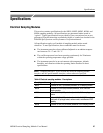
This section contains specifications for the 80E01, 80E02, 80E03, 80E04, and
80E06 sampling modules. All specifications are guaranteed unless noted as
“typical.” Typical specifications are provided for your convenience but are not
guaranteed. Specifications that are marked with the n symbol are checked in the
DSA8200 Specifications and Performance Verification manual.
All specifications apply to all models of sampling module unless noted
otherwise. To meet specifications, three conditions must first be met:
H The instrument must have been calibrated/adjusted at an ambient tempera-
ture between +20 _C and +30 _C.
H The oscilloscope must have been operating continuously for 20 minutes
within the operating temperature range specified.
H The instrument must be in an environment with temperature, altitude,
humidity, and vibration within the operating limits described in these
specifications.
NOTE. “Sampling Interface” refers to both the electrical sampling module
interface and the optical module interface, unless otherwise specified.
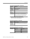
Table 6: Electrical sampling modules - Descriptions
Sampling m odule Description
80E01 1 channel 50 GHz (7 ps risetime) bandwidth, 50 Ω sampling module.
80E02 2 channel 12.5 GHz (28 ps risetime) bandwidth, 50 Ω,lownoise
sampling module.
80E03 2 channel 20 GHz (17.5 ps risetime) bandwidth, 50 Ω sampling
module.
80E04 2 channel 20 GHz (17.5 ps risetime) bandwidth, 50 Ω TDR/sampling
module with 35 ps single ended, common mode, and differential TDR
capability.
80E06 1 channel 70 GHz (5.0 ps risetime) bandwidth, 50 Ω sampling module.


