


Reference
28
80E00 Electrical Sampling Modules User Manual
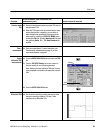
The reflections that a TDR displays and measures are caused by changes in the
impedance of the path of the step (circuit board, cable, or integrated circuit). Any
significant change in impedance will cause a reflection. As an example, if an
open solder connection exists on a circuit board, you can see that change with
TDR. TDR also displays changes in the conductor resistance. For example, if
there is corrosion in a joint and there is high resistance at that point, this is seen
by a TDR. TDR also displays changes in capacitance.
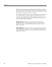
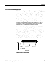
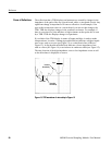
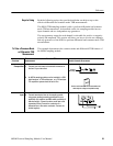
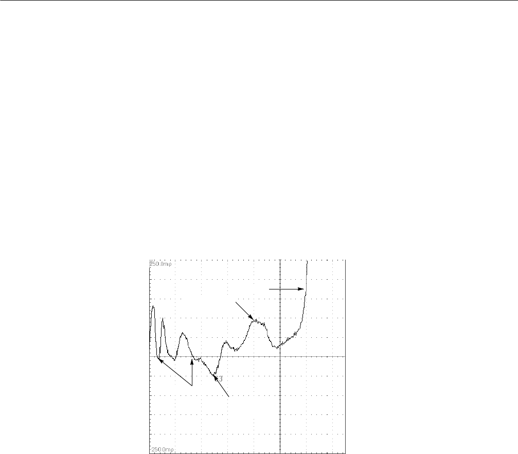
If you think of the TDR display in terms of bumps and dips, it tends to make
interpretation a lot easier. A bump (upward deflection) indicates a higher-imped-
ance event, such as an open (see Figure 13) or a reduction in line width (see
Figure 12). A dip (downward deflection) indicates a lower-impedance event,
such as a short (see Figure 14) or an increase in conductor width (see Figure 12).
The time location of the high-impedance event or low-impedance event as well
as the delta times is displayed on screen.
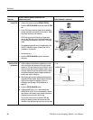
Open
Connector
Capacitive
discontinuity
Inductive
discontinuity
Figure 13: TDR waveform of microstrip in Figure 12
Cause of Reflections