


Reference
80E00 Electrical Sampling Modules User Manual
37
When making differential or common-mode TDR measurements, the two steps
must arrive at the same time at the reference plane (usually the connection point
to the device under test). To adjust the TDR step deskew perform the following
steps:
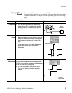
Overview Adjusting TDR step deskew Control elements & resources
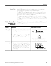
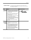
Prerequisites 1. Either disconnect the transmission cables from the
device under test (DUT) at the point where the cables
connect to the device, or short both lines to ground at
the DUT. Shorted lines are shown in this procedure.
2. Set channel deskew to zero.
Device
under test
Adjust TDR step
deskew
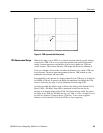
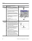
3. Then, from the TDR setup window, adjust the TDR
Manual Step Deskew so that the propagation delay (T0)
between the incident edges is equal to the propagation
delay between the reflected edges, as shown in the
figure.
If using a math function, do not adjust the step more;
instead, adjust channel deskew as shown in the
following step.
-- T 0
Step arrival at DUT
+T0
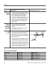
Adjust channel
deskew
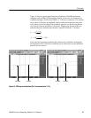
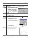
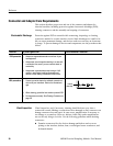
For some measurements, math summing and comparisons,
you may want to visually line up the reflection edges of both
TDR steps, even though you have delayed the step assertion
time for one channel in the preceding step.
4. To do this, first deskew the steps as shown above.
Then, from the Vertical setup window, deskew the
channels.
0V
0V
Align using
channel deskew
Adjusting TDR Step
Deskew