


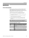

Specifications
50
80E00 Electrical Sampling Modules User Manual
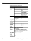
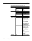
Table 7: Electrical sampling modules - Signal acquisition (cont.)
Specifications Characteristics
n Random noise, Sampling module Noise
,
displayed
80E01 ≤ 2.3 mV
RMS
1.8 mV
RMS
,typical
80E02 ≤ 800 V
RMS
400 V
RMS
,typical
n Random noise,
displayed
80E03 and 80E04 ≤ 1.2 mV
RMS
600 V
RMS
,typical
n Random noise,
displayed
80E06 ≤ 2.4 mV
RMS
≤ 1.8 mV
RMS
,typical
Offset range
1
±1.6 V
1
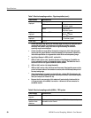
Vertical operating range defines the maximum range over which the offset plus peak
input signal can operate. The offset may be limited as a function of vertical
sensitivity and dynamic range, such that no signal exceeding the maximum
operating range can be displayed.
2
Vertical nondestruct range defines the maxi mum range over which offset plus peak
input signal can operate without irreversible damage to the instrument. Operation to
instrument specification is not guarantied outside of the vertical operating range.
3
Input Signal Ranges in IEEE std 1057, section 2.2.1.
4
IEEE std 1057, section 4.8.2, Transition Duration of Step Response. The 80E01 rise
time is calculated from the 0.35 bandwidth-risetime product. The 80E06 rise time is
calculated from the 0.35 typical bandwidth-risetime product.
5
IEEE std 1057, section 4.6, Analog Bandwidth.
6
IEEE std 1057, section 4.8.4, Overshoot and Precursors. Step transition occurs at the
point of minimum radius of the waveform curvature, after the 50% amplitude point of
the step leading edge.
7
When tested using a V-connector equipped 50-ohm, ultrafast PIN Photodetector with
greater than 50 GHz bandwidth, which is driven by an ul trafast, mode-locked impulse
laser (for example, the Calmar FPL-01).
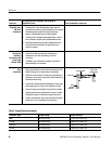
8
Because the 2.4 mm connector of this adapter will mechanically interface with the
1.85 m m connector of the 80E06, it serves as a 1.85 mm-to-2.92 mm connector for
the 80E06 module.
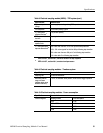
Table 8: Electrical sampling module (80E04) - TDR system
Specifications Characteristics
Number of TDR
channels
2, one per channel
TDR polarity and
operation mode
selections
Positive polarity, negative polarity, and TDR off are independently
selectable for each channel