


Reference
80E00 Electrical Sampling Modules User Manual
35
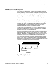
Overview Control elements & resources
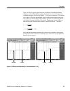
To take a comm on mode or differential TDR
measurement (cont.)
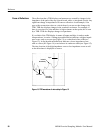
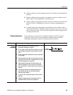
Common mode
TDR
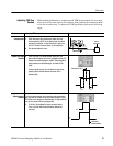
13. Notice that both channels assert a positive TDR step for
common-mode TDR.
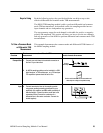
14. When t he TDR steps on the two channels are the same
polarity (both positive or negative), you can define a
math waveform that represents the average common-
mode si gnal by pressing the VERTICAL MENU button,
selecting the Vert tab, selecting Waveform M1, On, and
then sel ecting Define, C1, +, C2, Math Waveform On,
and OK.
Take a
measurement
15. Take your measurement. For more information, see
Take automatic measurements on page 25, or Take
cursor measurements on page 26.
Enable
differential TDR
measurements
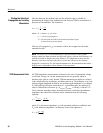
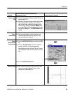
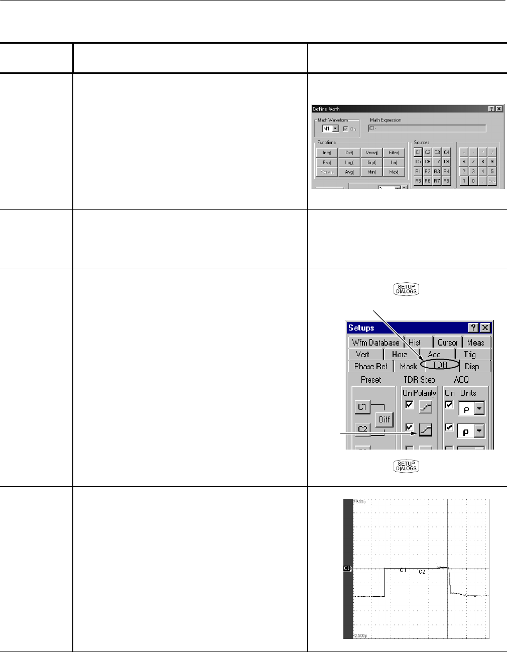
16. Press the SETUP DIALOGS button and select the TDR
tab.
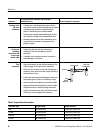
17. Click the TDR STEP Polarity box for one channel to
invert the polarity of one of the step generators.
Note: Although you have inverted a TDR step, the step
is onl y displayed inverted when the acquisition units are
Volts.
18. Press the SETUP DIALOGS button.
Step
polarity
TDR tab
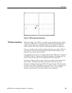
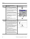
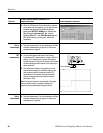
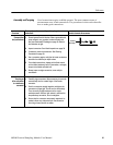
Differential TDR 19. One channel is asserting a positive s tep and the other
channel i s asserting a negative TDR step. These
conditions set up differential TDR.