


Reference
80E00 Electrical Sampling Modules User Manual
43
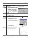
TDR Impedance Measuring
This stand-alone application implements the TDR calibration procedure(s)
specified by the IPC--TM--650 test methodology. It enhances the accuracy and
repeatability of impedance measurements by calibrating the test setup to correct
for losses and impedance discontinuities. Additionally, this application can use a
database for storing TDR measurements. This application is not installed on your
instrument, but it can be installed from the 8000 Series Demo Application CD
shipped with the instrument.
For more information see T DR Impedance-Measuring Application Online Help.
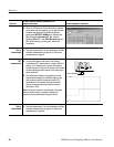
Detecting Blown Inputs
Because of their technology, high-bandwidth sampling modules are vulnerable to
damage through static discharge and overvoltages (EOS) to the input.
Damage can occur instantaneously. Under most conditions when EOS damage
occurs, the trace will be flat. It typically involves short-period, high-current
discharge. The damages can be blown diodes, as indicated by large offset, or no
response to input.
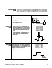
To check for damage, use one of the following procedures:
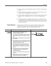
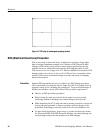
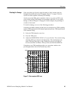
H If checking an 80E04 sampling module and your instrument has TDR
capability, attach a 50 Ω termination to the channel input and perform a TDR
measurement of the attached fitting. Adjust the HORIZONTAL SCALE to
500 ns per division. This should display the entire TDR step from edge to
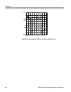
edge. Display the step top at 40 mρ per division and check for flatness. If the
top is bowed, sagged, hooked, or tilted, assume static has damaged the
module and service is required. See Figure 16 on page 44.
H If checking a non-TDR sampling module, use a procedure similar to the
preceding procedure, but use an external step source.
Checking For Damage