Reference
80E00 Electrical Sampling Modules User Manual
23
Overview Control elements & resourcesTo take a TDR measurement (cont.)
Set other TDR
parameters
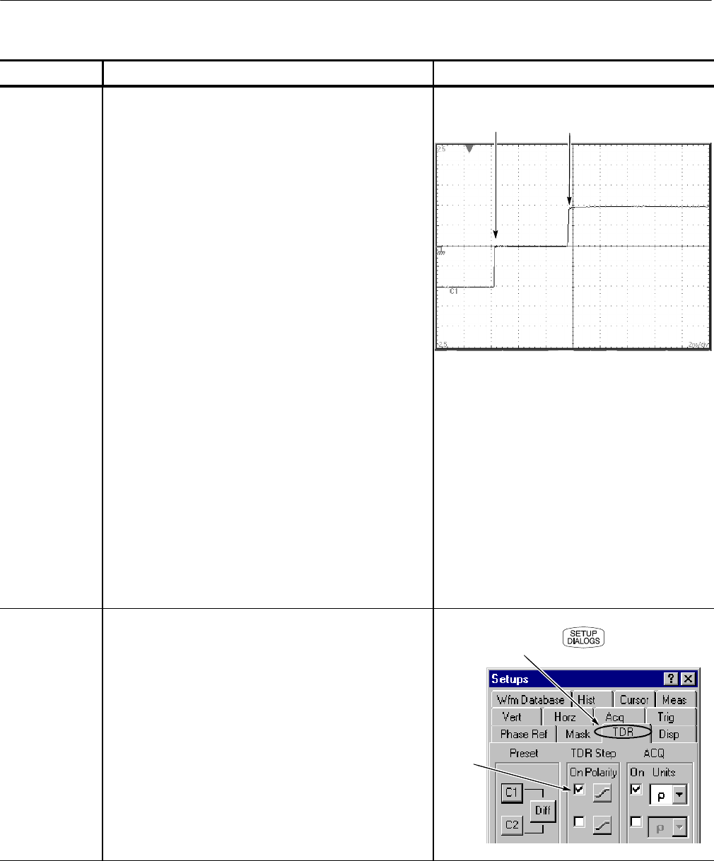
7. Adjust the VERTICAL SCALE (500 mρ/div in this
example) and HORIZONTAL SCALE (2 ns/div in this
example) to show a trace similar to that shown. Leave at
least one division of baseline trace to the left of the
first rise.
The fi rst rise of this waveform is the incident TDR step
leaving the sampling module; the second rise is the
reflect ion of the step returning from the end of the cable.
For your device under test (DUT), you may need to
adjust the Horizontal SCALE, POSITION, and
Reference to display the reflections from your DUT near
the left of the graticule.
To locate reflections from your DUT, disconnect your
probe or cable at the DUT and look for the reflection
from the open end of the probe or cable.
Assuming the line to be tested is an open-end microstrip
on a circuit board and that your probe or cable is now
connected to the line, you will see the new open
reflect ion t o the right according to the length of the line.
There may be a visible disturbance where the
connection is made to the board (for example, see
Figure 12 on page 27). The area between the entry to
the board and the open reflection at the end of the board
is the target area for your TDR measurements. Adjust
Vertical SCALE, Vertical POSITION, Horizontal SCALE,
and Horizontal POSITION as necessary for a good
quality di splay of the measurement area.
ρ
ρ
Reflection f
om
open end of cable
Incident
TDR step
Changing TDR
graticule units
8. The units of measure commonly used in TDR are units
of rho (ρ), measured on the vertical axis. You can
change the measurement units by using the ACQ Units
selector i n the TDR Setups dialog box.
9. Press the SETUP DIALOGS button, and select the TDR
tab.
10. Select either V for Volts, ρ for rho, or Ω for ohms.
Enable
TDR
TDR tab


