


17
Data Acquisition and Stimulus
State/Timing Modules
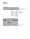
Selecting the Correct Modules
to Meet Your Needs
Selecting the proper logic analyzer
modules for your needs requires a
series of choices concerning
performance, cost, and the amount of
data you will be able to capture. The
following table explains these factors
in greater detail.
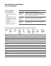
Considerations for Choosing Modules
Microprocessor/ Will you be using an analysis probe for a particular processor or bus? If so, a good starting point is the document Processor
Bus Support and Bus Support for Agilent Technologies Logic Analyzers, publication number 5966-4365E, available on the worldwide web
at www.agilent.com/find/logicanalyzer. This document provides the number of channels and state speed required for any
particular analysis probe. It also indicates which analysis modules are supported and how many are required.
State Speed • State analysis uses a clock or strobe signal from your system under test to determine when to sample. Because state
analysis samples are synchronous with the system under test, they provide a view of how your system is executing. You can
use state analysis to capture bus cycles from a microprocessor or I/0 bus and convert the data into processor mnemonics
or bus transactions using an Agilent Technologies inverse assembler.
• Select a state acquisition system that provides the speed and headroom you need without breaking your budget. Remember
that a microprocessor will have an internal core frequency that is normally 2X-5X the speed of the external bus.
Headroom You may realize a better return on your investment if you consider possible future needs when purchasing analysis modules.
The things to consider are primarily state speed and memory depth.
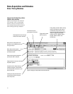
Setup/Hold • Logic analyzers require time for the data at the inputs to become valid (setup time), and time to capture the data (hold time).
A lengthy setup and hold can make the difference between capturing valid data or data in transition.
• Your device under test will ensure that data is valid on the bus for a defined length of time. This is known as the data valid
window. Your target's data valid window must be large enough to meet the setup/hold specifications of the logic analyzer.
The data valid window of most devices is generally less than half of the clock period. Don't be fooled by "typical" setup and
hold specifications for logic analyzers.
• As bus speeds increase, the time window during which data is stable decreases. Jitter, skew, and pattern-dependent ISI
add more uncertainty and consume a greater portion of the data-valid window at high speeds. A logic analyzer with
adjustable setup/hold with fine position resolution provides unparalleled measurement accuracy at high frequencies.
Timing Resolution Timing analysis uses the logic analyzer's internal clock to determine when to sample. Since timing analysis samples
asynchronously to the system under test, you should consider what accuracy you will need to verify your system.
Accuracy is made up of two elements: sample speed and channel-to-channel skew. Remember to evaluate both of these
elements and be careful of logic analyzers that have a fast sample speed with a large channel-to-channel skew.
Transitional Timing If your system has bursts of activity followed by times with little activity, you can use transitional timing to capture a longer
trace. In transitional timing, the analyzer samples data at regular intervals, but only stores the data when there is a transition
on one of the signals.