


36
Data Acquisition and Stimulus
Pattern Generation Modules
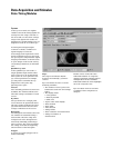
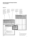
"User Macro" and "Loop" Simplify
Creation of Stimulus Programs
User macros permit you to define a
pattern sequence once, then insert
the macro by name wherever it is
needed. Passing parameters to the
macro will allow you to create a more
generic macro. For each call to the
macro you can specify unique values
for the parameters. Each macro can
have up to 10 parameters. Up to 100
different macros can be defined for
use in a single stimulus program.
Loops enable you to repeat a defined
block of vectors for a specified
number of times. The repeat counter
can be any value from 1 to 20,000.
Loops and macros can be nested,
except that a macro can not be nested
within another macro. When nested,
each invocation of a loop or a macro
is counted towards the 1,000 invoca-
tion limit. At compile time, loops and
macros are expanded in memory to a
linear sequence.
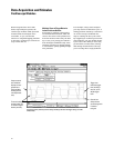
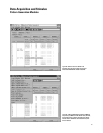
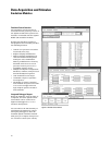
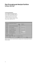
Convenient Data Entry and Editing
Feature
You can conveniently enter patterns
in hex, octal, binary, decimal, and
two's complement bases. The data
associated with an individual label
can be viewed with multiple radixes
to simplify data entry. Delete, Insert,
Copy, and Merge commands are
provided for easy editing. Fast and
convenient Pattern Fills give the
programmer useful test patterns with
a few key strokes. Fixed, Count,
Rotate, Toggle, and Random are
available to quickly create a test
pattern, such as "walking ones".
Pattern parameters, such as Step
Size and Repeat Frequency, can be
specified in the pattern setup.
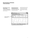
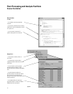
ASCII Input File Format: Your Design
Tool Connection
The 16720A supports an ASCII file
format to facilitate connectivity to
other tools in your design environ-
ment. Because the ASCII format does
not support the instructions listed
earlier, they cannot be edited into the
ASCII file. User macros and loops
also are not supported, so the vectors
need to be fully expanded in the
ASCII file. Many design tools will
generate ASCII files and output the
vectors in this linear sequence. Data
must be in Hex format, and each label
must represent a set of contiguous
output channels. Data in this ASCII
format is limited to 1 MVectors in
the 16720A.
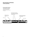
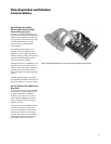
Configuration
The 16720A pattern generators
require a single slot in a logic
analysis system frame. The pattern
generator operates with the clock
pods, data pods, and lead sets
described later in this section. At
least one clock pod and one data pod
must be selected to configure a func-
tional system. Users can select from a
variety of pods to provide the signal
source needed for their logic devices.
The data pods, clock pods and data
cables use standard connectors. The
electrical characteristics of the data
cables also are described for users
with specialized applications who
want to avoid the use of a data pod.
The 16720A can be configured in
systems with up to five cards for a
total of 240 channels of stimulus.
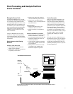
Direct Connection to Your Target
System
The pattern generator pods can be
directly connected to a standard
connector on your target system. Use
a 3M brand #2520 Series, or similar
connector. The 16720A clock or data
pods will plug right in. Short, flat
cable jumpers can be used if the
clearance around the connector is
limited. Use a 3M #3365/20, or equiv-
alent, ribbon cable; a 3M #4620
Series, or equivalent, connector on
the 16720A pod end of the cable; and
a 3M #3421 Series, or equivalent,
connector at your target system end
of the cable.
Probing Accessories
The probe tips of the Agilent 10474A,
10347A, and 10498A lead sets plug
directly into any 0.1 inch grid with
0.026 inch to 0.033 inch diameter
round pins or 0.025 inch square pins.
These probe tips work with the
Agilent 5090-4356 surface mount
grabbers and with the Agilent
5959-0288 through-hole grabbers.
Other compatible probing accessories
are listed in ordering information on
page 121.