


33
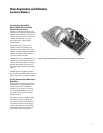
Data Acquisition and Stimulus
Pattern Generation Modules
Digital Stimulus and Response in a
Single Instrument
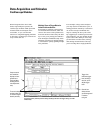
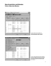
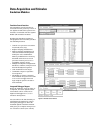
Configure the logic analysis system to
provide both stimulus and response
in a single instrument. For example,
the pattern generator can simulate a
circuit initialization sequence and
then signal the state or timing analyz-
er to begin measurements. Use the
compare mode on the state analyzer
to determine if the circuit or subsys-
tem is functioning as expected. An
oscilloscope module can help locate
the source of timing problems or
troubleshoot signal problems due to
noise, ringing, overshoot, crosstalk,
or simultaneous switching.
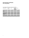
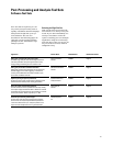
Key Characteristics
Agilent Model 16720A
Maximum clock (full/half channel) 180/300 MHz
Number of data channels (full/half channel) 48/24 Channels
Memory depth (full/half channels) 8/16 MVectors
Maximum vector width 240/120 Bits
(5 module system, full/half channel)
Logic levels supported TTL, 3-state TTL, 3.3V, 1.8V, 3-state CMOS, ECL,
5V PECL, 3.3V LVPECL, LVDS
Maximum binary vector set size 16 MVectors (24 channels)
Editable ASCII vector set size 1 MVectors
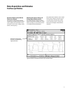
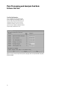
Parallel Testing of Subsystems
Reduces Time to Market
By testing system subcomponents
before they are complete, you can fix
problems earlier in the development
process. Use the Agilent 16720A as a
substitute for missing boards,
integrated circuits (ICs), or buses
instead of waiting for the missing
pieces. Software engineers can create
infrequently encountered test
conditions and verify that their code
works—before complete hardware is
available. Hardware engineers can
generate the patterns necessary to
put their circuit in the desired state,
operate the circuit at full speed or
step the circuit through a series
of states.