


66
Post-Processing and Analysis Tool Sets
Serial Analysis
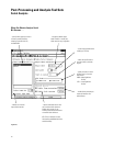
Product Characteristics
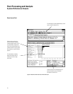
Data Sources
All state and timing measurement
modules supported by the 16700
Series logic analysis systems serve
without modification as data sources
for the B4601B serial analysis tool
set. The particular measurement
module used determines time resolu-
tion and accuracy. Sample rate, chan-
nel count, memory depth and trigger-
ing are controlled by the user inde-
pendent of the serial analysis tool.
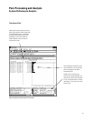
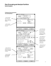
Because every trace is non-intrusive,
and every event captured in the trace
is time-stamped, you can correlate
activity from your serial bus with
other events in the target system.
The Agilent Technologies 16720A and
16522A pattern generator modules
can be used to generate your own
serial test data.
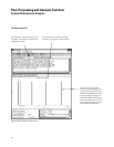
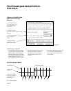
Maximum Parallel Word Width
32 bits
Parallel Data Display Types
Binary, Octal, Hex, Decimal, ASCII,
Twos Complement
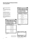
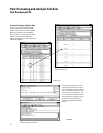
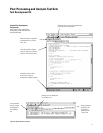
Off-line Analysis and Post-Processing
All measurements can be saved using
the file out tool. Data can be recalled
at any time for later analysis using
any analysis or display tool. Serial
measurement data can be exported to
your host computer as ASCII files.
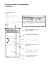
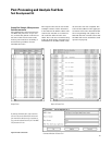
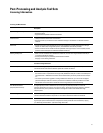
Serial Measurement Characteristics
16517A/18A 16710A/11A/12A 16715A 16716A 16717A/18A/19A 16750A/51A/52A
Maximum serial Clocked data [1] 64 Kbits 8 Kbits/32 Kbits/ 2 Mbits 512 Mbits 2 Mbits/8 Mbits/ 4 Mbits/16
Mbits/
trace depth 128 Kbits 32 Mbits 32 Mbits
Unclocked data [2] 16-32 Kbits 4 Kbits/16Kbits/ 1 Mbit 256 Mbit 1 Mbit/4 Mbits/ 2 Mbits/8 Mbits/
64 Kbits 16 Mbits 16 Mbits
Maximum serial Clocked data [3] 1 Gbit/s 100 Mbits/s 167 Mbits/s 167 Mbits/s 333 Mbits/s 400 Mbits/s
bus frequency
Unclocked data [4] 1 Gbit/s 125 Mbits/s 167 Mbits/s 167 Mbits/s 167 Mbits/s 200 Mbits/s
Minimum serial Clocked data 20 Mbit/s No limit No limit No limit No limit No limit
bus frequency
Unclocked data [5] 765 Mbits/s 5 Kbits/s 50 bits/s 50 bits/s 50 bits/s 50 bits/s
Information in Table above calculated according to notes [1] to [5]
[1] =Maximum State Memory Depth
[2] =Maximum Timing Memory Depth/4
[3] =Maximum State Frequency
[4] =Maximum Timing Frequency/4
[5] =1/(Maximum sample period x 20)