


27
Data Acquisition and Stimulus
State/Timing Modules
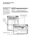
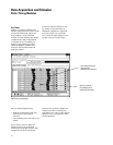
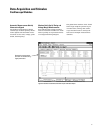
Agilent 16760A: Extending Logic
Analysis to New Realms
• Differential inputs (single-ended
probes also available).
• State analysis up to 1.5 Gb/s.
• Setup-and-hold time of 500 ps.
• Input signal amplitude as low as
200 mV p-p.
Logic analysis at state speeds up to
1.5 Gb/s imposes a stringent set of
criteria for a logic analyzer.
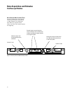
• Probing
Agilent’s 16760A uses an innovative
probing system with only 1.5 pF of
probe tip capacitance, including the
connector. The connector is a joint
design between Agilent and Samtec,
optimized especially for logic analysis
measurements.
Ground pins located between every
pair of signal pins provide excellent
channel-to-channel isolation at high
speeds.
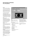
• Setup and hold
As state speeds go up, the data valid
window shrinks. To make reliable
measurements, a logic analyzer’s
combined setup and hold window
must be smaller than the data valid
window of the signals it is acquiring.
Agilent’s 16760A has a combined
setup and hold time of 500 ps to
match the data valid window of
very high-speed buses.
To position the analyzer’s setup-and-
hold window inside the data valid
window requires very fine adjust-
ment resolution. The 16760A gives
you the ability to position the setup-
and-hold window with 10 ps resolu-
tion.
• Small-amplitude signals
Many high-speed designs use small
signal amplitudes to limit slew rates
and reduce power. Agilent’s 16760A
can make reliable measurements on
signals as small as 200 mV p-p.
• Differential signals
Many high-speed designs use differen-
tial signaling to minimize simultane-
ous switching noise and to provide
immunity to crosstalk and noise. The
Agilent 16760A has differential inputs
to allow you to acquire differential
signals with complete confidence.
Single-ended probes are also available.
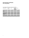
Agilent helps you get started in the
design stage.
To probe high-speed signals with a
logic analyzer, you need to design the
probe in when you are designing your
PC board. The following document
from Agilent will help you design your
system to take maximum advantage
of the capabilities of the 16760A logic
analyzer:
• Logic signal standards supported
TTL LVTTL
HSTL Class I & II HSTL CLass III & IV
SSTL2 SSTL3
AGP-2X LVCMOS 1.5V
LVCMOS 1.8V LVCMOS 2.5V
LVCMOS3.3V CMOS 5V
ECL LVPECL
PECL
User defined from -3V to +5V in 10mV
increments
Publication Title Description Publication Number
User’s Guide, Agilent Technologies E5378A, E5379A, and Mechanical drawings, electrical models, 16760-97007
E5380A Probes for the 16760A Logic Analyzer general information on probes for the 16760A
Designing High-Speed Digital Systems for Guidelines and design examples for designing 5988-2989EN
Logic Analyzer Probing logic analyzers probing into your target system