


96
State/Timing Modules Specifications and
Characteristics
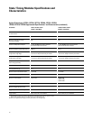
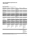
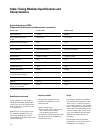
Specifications for Each Input
Parameter Minimum Description/Notes
800, 1250, 1500 Mb/s modes 200, 400 Mb/s modes
Data tWidth* 500 ps 1.25 ns Eye width in system under test [2]
to Clock tSetup 250 ps 625 ps Data setup time required before tSample
tHold 250 ps 625 ps Data hold time required after tSample
All vHeight [1] 100mV 100mV E5379A 100-pin differential probe [3]
Inputs 250 mV 250 mV E5378A 100-pin single-ended probe [4],
E5382A single-ended flying-lead probe set
300mV 300mV E5380A 38-pin single-ended probe
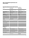
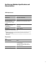
User Adjustable Settings for Each Input
Parameter Adjustment Range
1500 Mb/s mode 1250 Mb/s mode 800 Mb/s mode 400 Mb/s mode 200 Mb/s mode
Data Adjustment Resolution 10 ps 10 ps 10 ps 100 ps 100 ps
to Clock tSample [5] 0 to +4 ns -2.5 to +2/5 ns -2.5 to +2/5 ns -3.2 to +3.2 ns -3.5 to +3 ns
All vThreshold [6] 10 mV resolution 10 mV resolution 10 mV resolution 10 mV resolution 10 mV resolution
Inputs -3 to +5 V -3 to +5 V -3 to +5 V -3 to +5 V -3 to +5 V
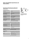
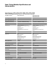
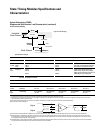
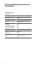
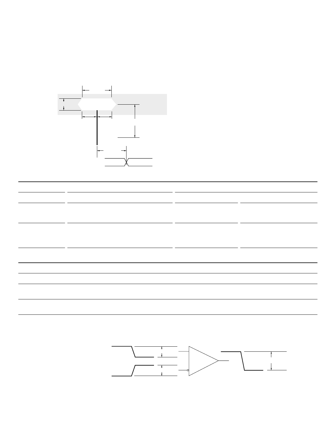
Individual
Data Channel
vHeight
tWidth
tSetup
Sampling
Position
Clock Channel Note (1)
tHold
vThreshold*
*User Adjustable
—0V—
tSample*
Data Eye
Figure 6.17. Data Sampling.
* All specifications noted by an asterisk in the table are the performance standards against which the product is tested.
[1] The analyzer can be configured to sample on the rising edge, the falling edge, or both edges of the clock. If both edges are used with a single ended clock input, take care to set the
clock threshold accurately to avoid phase error.
[2] Eye width and height are specified at the probe tip. Eye width as measured by eye finder in the analyzer may be less, and still sample reliably.
[3] For each side of a differential signal.
[4] The clock inputs in the E5378A and the E5382A may be connected differentially or single ended. Use the E5379A vHeight spec for clock channel(s) connected differentially.
[5] Sample positions are independently adjustable for each data channel input. A negative sample position causes the input to be synchronously sampled by that amount before each
active clock edge. A positive sample position causes the input to be synchronously sampled by that amount after each active clock edge. A sampling position of zero causes synchro-
nous sampling coincident with each active clock edge.
[6] Threshold applies to single-ended input signals. Thresholds are independently adjustable for the clock input of each pod and for each set of 16 data inputs for each pod. Threshold lim-
its apply to both the internal reference and to the external reference input on the E5378A.
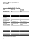
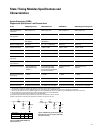
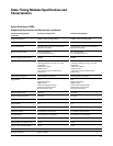
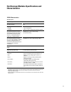
vHeight
2X vHeight
vHeight
⌺
nSignal
pSignal
——0V——
Agilent Technologies 16760A
Supplemental Specifications* and Characteristics (continued)
Synchronous Data Sampling