


34
Data Acquisition and Stimulus
Pattern Generation Modules
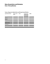
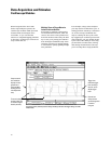
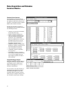
Vectors Up To 240 Bits Wide
Vectors are defined as a "row" of
labeled data values, with each data
value from one to 32 bits wide. Each
vector is output on the rising edge of
the clock.
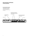
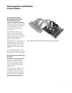
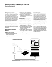
Up to five, 48-channel 16720A mod-
ules can be interconnected within a
16700 Series mainframe or expansion
frame. This configuration supports
vectors of any width up to 240 bits
with excellent channel-to-channel
skew characteristics (see specific
data pod characteristics in Pattern
Generation Modules Specifications
starting on page 105). The modules
operate as one time-base with one
master clock pod. Multiple modules
also can be configured to operate
independently with individual clocks
controlling each module.
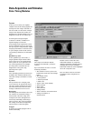
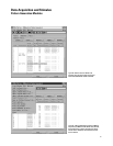
Depth Up to 16 MVectors
With the 16720A pattern generator,
you can load and run up to
16 MVectors of stimulus. Depth on
this scale is most useful when cou-
pled with powerful stimulus
generated by electronic design
automation tools, such as
SynaptiCAD's WaveFormer and
VeriLogger. These tools create
stimulus using a combination of
graphically drawn signals, timing
parameters that constrain edges,
clock signals, and temporal and
Boolean equations for describing
complex signal behavior. The
stimulus also can be created from
design simulation waveforms. To take
advantage of the full depth of the
16720A pattern generator, data must
be loaded into the module in the
Pattern Generator Binary (.PGB) for-
mat. The SynaptiCAD tools allow you
to convert .VCD files into .PGB files
directly, offering you an integrated
solution that saves you time.
Synchronized Clock Output
You can output data synchronized to
either an internal or external clock.
The external clock is input via a clock
pod, and has no minimum frequency
(other than a 2 ns minimum high
time).
The internal clock is selectable
between 1 MHz and 300 MHz in
1 MHz steps. A Clock Out signal is
available from the clock pod and can
be used as an edge strobe with a
variable delay of up to 8 ns.
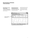
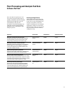
Initialize (INIT) Block for
Repetitive Runs
When running repetitively, the vec-
tors in the initialize (init) sequence
are output only once, while the main
sequence is output as a continually
repeating sequence. This "init"
sequence is very useful when the
circuit or subsystem needs to be
initialized. The repetitive run capabil-
ity is especially helpful when operat-
ing the stimulus module independent
of the other modules in the logic
analysis system.
"Signal IMB" Coordinates System
Module Activity
A "Signal IMB" (intermodule bus)
instruction acts as a trigger arming
event for other logic analysis modules
to begin measurements. IMB setup
and trigger setup of the other logic
analysis modules determine the
action initiated by "Signal IMB".
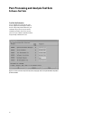
"Wait" for Input Pattern
The clock pod also accepts a 3-bit
input pattern. These inputs are level-
sensed so that any number of "Wait"
instructions can be inserted into a
stimulus program. Up to four pattern
conditions can be defined from the
OR-ing of the eight possible 3-bit
input patterns. A "Wait" also can be
defined to wait for an intermodule
bus event. This intermodule bus
event signal can come from any other
module in the logic analysis system.