


12
Panel Descriptions
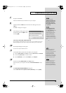
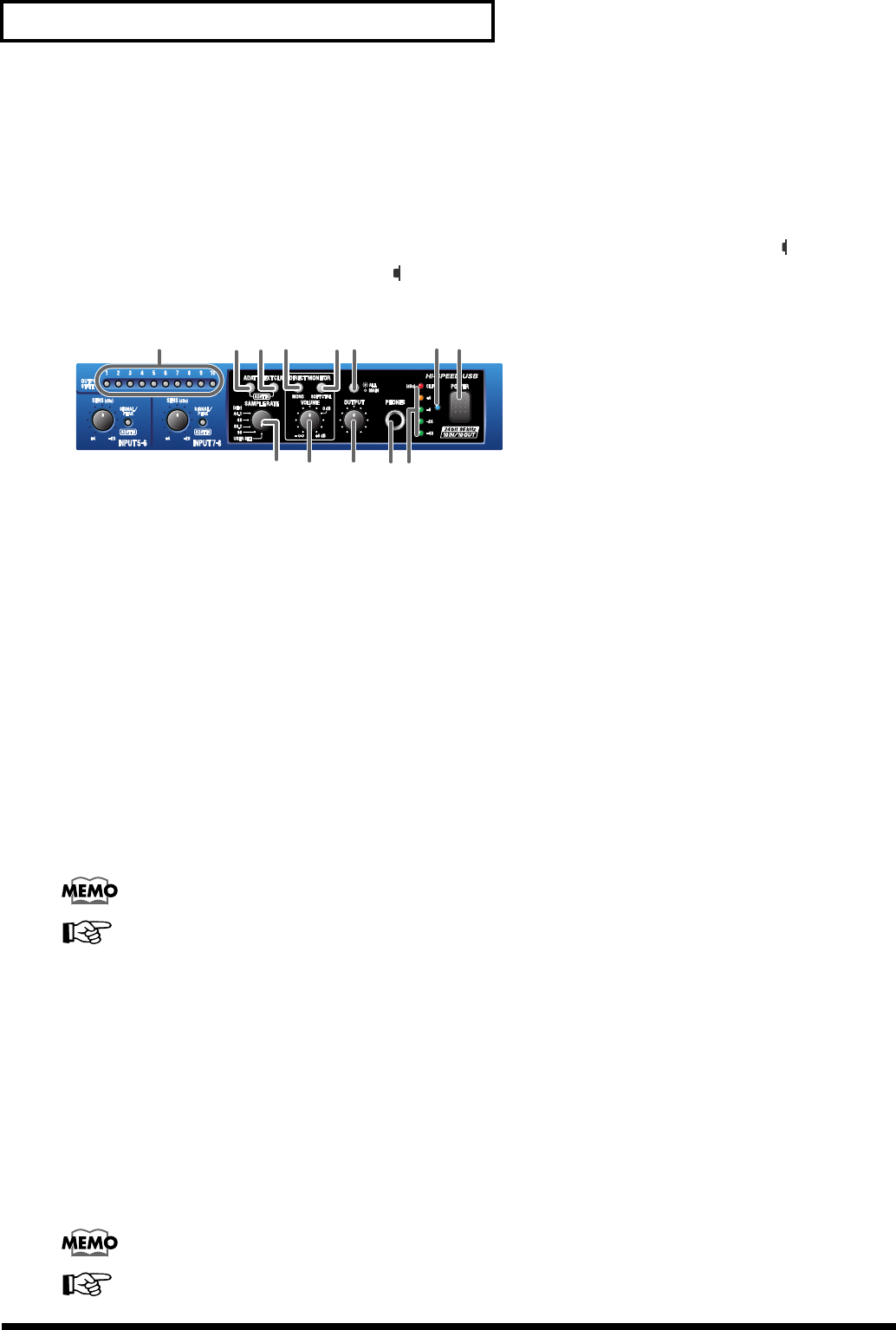
5.
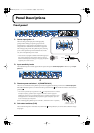
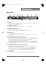
Input peak indicators
These indicate whether distortion is occurring in the sound being input to each input jack. The peak indicators will
light red at a level before the sound begins to distort (-6 dB). Adjust the corresponding
input sensitivity knob
or the
output level of your equipment so that the peak indicators do not light red.
6.
Input impedance select switch
For the phone jack input of
combo input jack 3
, you can select either high impedance (Hi-Z (button in the inward
position)) or low impedance (Lo-Z (button in the outward position)), as appropriate for the device that is
connected. Select high impedance (Hi-Z) if you have connected a guitar or bass.
fig.direct-monitor
7.
Output indicators
If audio data is being output from the UA-1000, the output indicator for the jack from which audio data is being
output will light. For example, if audio data is being output from output jack 1, output indicator
“1”
will light green.
Indicators
“9”
and
“10”
will light to indicate output from the digital output connector.
This provides a convenient way to check the settings of the UA-1000’s internal patch bay. For details, refer to
“Internal blocks of the UA-1000”
(p. 36).
8.
ADAT mode switch
When you press the ADAT mode switch, the ADAT mode switch will light and the UA-1000 will be in ADAT Output
mode; ADAT format signals will be output from the optical digital output jack.
If you simultaneously press the ADAT mode switch and the external clock switch, the PEAK/SIG/ADAT IN
indicators will all light orange, and the UA-1000 will be in ADAT Input/Output mode; ADAT format signals will be
input from the optical input jack.
* If you are using ADAT mode, you must set the UA-1000 to 44.1 kHz or 48 kHz. If a setting other than 44.1 kHz or 48 kHz is
selected, ADAT mode will not be available; pressing the ADAT mode switch will not cause the ADAT mode switch to light.
Turning off the power of the UA-1000 will not change the setting of this switch.
For more about the ADAT mode switch, refer to
“About the ADAT mode switch and external clock
switch”
(p. 41).
9.
External clock switch
Turn this on if you want the UA-1000 to synchronize to a word clock signal from an external device or to a digital
signal from the digital input jack. If synchronization is occurring normally, the external clock switch will light, and
the UA-1000 will be in external clock mode. If the external clock switch is blinking, synchronization has not been
achieved.
You must be sure to input a signal which has the frequency that matches the setting of the sampling frequency select
switch.
* If both the word clock input connector and the digital input connector are connected simultaneously, the word clock input
connector will take priority.
* If you are recording a digital signal, the external clock switch must be turned on.
Turning off the power of the UA-1000 will not change the setting of this switch.
For more about the external clock switch, refer to
“About the ADAT mode switch and external clock
switch”
(p. 41).
7 8 11 129
10 13
15 16 17
14
1918
UA-1000_e.book 12 ページ 2003年8月6日 水曜日 午前11時52分