Defining the Control Room
Master RC to a series of control actions. Once you have created a Virtual Device layout, it can be
shared using the Import/Export XML function under the File menu.
After adding a Virtual Device to the room control tree
1
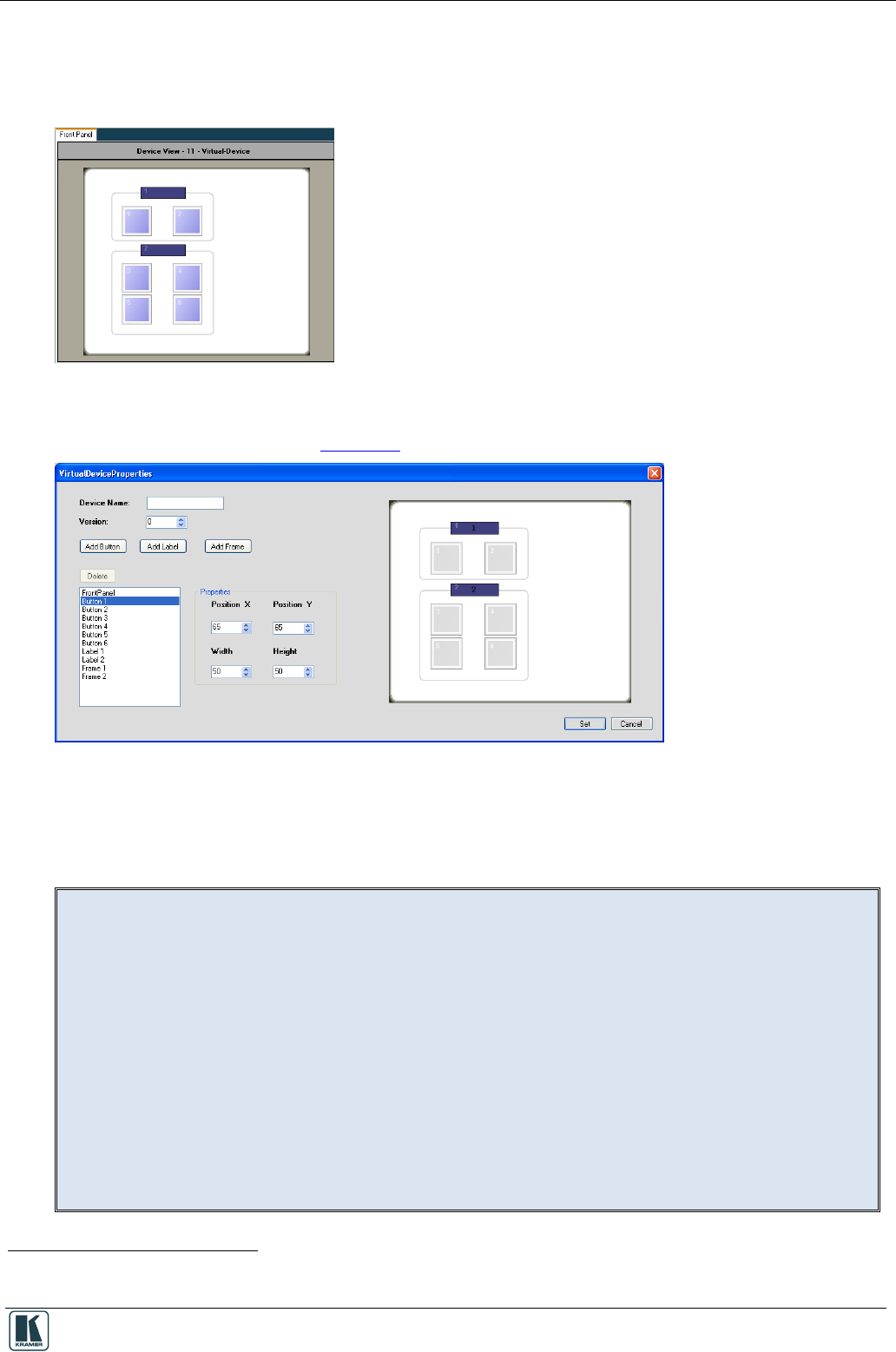
, the Front Panel area shows the basic Virtual
Device panel, that includes six buttons, two labels and two frames:
Figure 16: The Basic Virtual Device Front Panel
Right click the virtual device icon in the Control Room area to edit the device view via the Virtual
Device Properties window (see Figure 17)
Figure 17: The Virtual Device Properties Window
The Virtual Device Properties window lets you add or delete buttons
2
Note, that the exact appearance of the Virtual Device triggers layer in
K-Config has no real correlation to the look-and-feel and button layout of the Virtual Device
application running on the auxiliary device.
, labels (active text field) or
frames and set their position and size. You can also keep track of the virtual device versions by
setting the version number. This helps keep track of the version, especially when exporting a virtual
device.
In the virtual application, the developer will only address the ID Numbers of the buttons and
labels that were defined in K-Config as part of the Virtual Device, but their appearance in K-
Config have no significance or relation to the appearance of these buttons and labels in the
virtual application.
The appearance of the layout functions of the configured Virtual Device make the representation
of this trigger layer easy and straightforward to use when configuring Action lists in K-Config and
when addressing the buttons and labels in the Virtual Device applications.
Complete guidelines for creating the Virtual Device application can be found in the
" Virtual Device Build Guidelines" document, available on our Web site.
1 You can add up to two virtual devices (as determined by the Master RC)
2
You can add up to 32 buttons
