


KRAMER: SIMPLE CREATIVE TECHNOLOGY
Contents
ii
6.11.3 The Button Light Action Type 51
6.11.4 The Button Ignore Action Type 52
6.11.5 The Set LCD Label Action Type 52
6.11.6 The Switcher Command Action Type 53
6.11.7 The Power Amplifier Action Type 53
6.11.8 The Panel Lock Action Type 53
6.11.9 The Timer Start/Stop Action Type 54
6.11.10 The LEDs Light Action Type 54
6.11.11 The States Action Type 55
6.11.12 The Delay Action Type 57
7 Write the Configuration 58
8 Set K-NET IDs 59
9 The Driver Manager 60
9.1 Creating a Driver Command 61
9.1.1 Creating a Serial Command 61
9.1.2 Creating an IR Command 63
9.1.3 Creating Serial Range Commands 65
9.1.4 Kramer Machines Serial Commands 71
9.2 Defining Queries 73
9.2.1 Setting the Query Details (for Lamp Hours) 75
9.2.2 Setting the Power Query 78
10 The Kramer K-Config Menus 81
10.1 The File Menu 81
10.1.1 Starting a New Project 81
10.1.2 Saving a Project 82
10.1.3 Import/Export Devices 82
10.2 The Device Menu 84
10.2.1 Load Firmware 84
10.3 The Help Menu 86
11 Connecting the RC-6X Series Room Controller as a Standalone Device 86
12 Connecting via the ETHERNET 87
12.1 Connecting the ETHERNET Port directly to a PC (Crossover Cable) 87
12.2 Connecting the ETHERNET Port via a Network Hub (Straight-Through Cable) 87
Figures
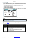
Figure 1: Media Room Components List 6
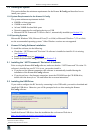
Figure 2: USB Driver Notice 7
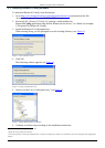
Figure 3: Driver Database Notice 8
Figure 4: Setting a Working Directory 8
Figure 5: Change Working Directory Window 8
Figure 6: USB Driver Installation Notice 9
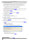
Figure 7: The Driver Manager Window Prior to Installing the Drivers 10
Figure 8: Importing the Driver Files 10
Figure 9: Loading the Drivers 11
Figure 10: Adding the Master Device 12
Figure 11: The Master Device View 12
Figure 12: The Auxiliary Device View 13
Figure 13: The Remote Control Device View 13
Figure 14: Configuration Mismatch Warning 13
Figure 15: Device Operations 14
Figure 16: The Basic Virtual Device Front Panel 15
Figure 17: The Virtual Device Properties Window 15
Figure 18: Custom Virtual Device Appearance in K-Config 16
Figure 19: Editing the Virtual Device Appearance (Step 1) 16
Figure 20: Editing the Virtual Device Appearance (Step 2) 16
Figure 21: The “DVD Control” Virtual Device Front Panel 17