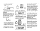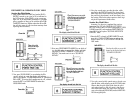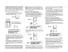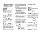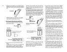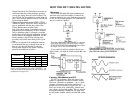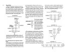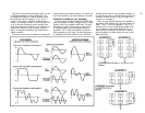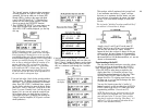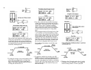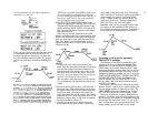
The results of using different frequency ratios, as well
as different algorithms, are shown graphically in the
accompanying illustration. In the left column, you see
the resulting waveforms created by 1:1,2:1 and 3:1
frequency ratios when a modulator is stacked atop a
carrier — for example, operators 1 and 2 in Algorithm 5
or 16. In the right column you see the resulting wave-
forms from these same 3 frequency ratios when the two
operators are side-by-side, both serving as carriers so
there is no frequency modulation, but instead there is
additive synthesis.
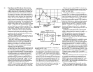
Still more variations can be achieved by changing the
relative output levels between operators; the greater the
level of the modulator, the more harmonics are present.
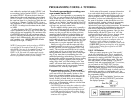
Feedback is available in every algorithm
Notice that every algorithm includes one FEEDBACK
path. The feedback is usually "wrapped around" a single
operator, with a few exceptions noted below. The feed-
back returns a portion of the operators output back to
an additional input on the same operator (except in
algorithms
#
4 &
#
6, where the feedback is returned to
the top modulator on the "stack". In effect, the operator
is modulating itself when feedback is used. While the
feedback paths are part of every algorithm, feedback is
not used in every voice; an editing function permits the
amount of feedback to be set to any of 8 values from
none (0) to a maximum (7).
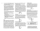
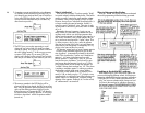
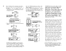
Often, the only difference between two algorithms is
the location of the feedback loop. This is true with algo-
rithms
#
3 and
#
4, and with algorithms
#
5 and
#
6, as
illustrated. If you were to switch between either of the
two algorithms in a pair with the feedback level at 0,
there would be no difference in the sound, whereas
with the feedback at a higher setting, the sound could
differ significantly.
25
If FEEDBACK is at 0, these two algorithms become
identical


