


91bu i l di ng A Pro64 ne tw ork
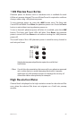
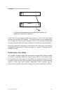
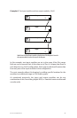
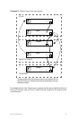
Example 5: One input module and two output modules in Manual Mode
B A
B A
Input
B A
Output
B A
Input
B A
Output
B A
Input
B A
Input
B A
Output
1 2
Merger
3 4 5 6 7 8 9 10
B A
B A
Input
B A
Output
B A
Input
B A
Output
B A
Input
B A
Input
B A
Output
1 2
Merger
3 4 5 6 7 8 9 10
B A
B A
Input
B A
Output
B A
Input
B A
Output
B A
Input
B A
Input
B A
Output
1 2
Merger
3 4 5 6 7 8 9 10
The input module transmits its audio data via Port A (marked with a square
surrounding the port name). Only the lower Pro64 output module can make
use of those audio channels.
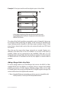
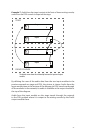
In the example above, showing I/O modules in the middle of a Pro64
network, the input module in the center of the diagram is set to transmit
its active audio data to Port A, using the A‑Net Slot range starting at 1. The
output module below it is set to listen to any A‑Net data that arrives on its
Port B. The output module at the top of the diagram is set to listen to data
arriving at its Port A.
Since the input module is directing its data to Port A, only the bottom
module can output the audio channels made active on the input module.
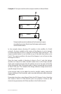
Again, the example assumes that all modules are set to the same A‑Net Slot
range. Remember that all network audio is always transmitted and received
at each A‑Net port. The module’s Slot Range selection simply tunes into a
specific range of channels.
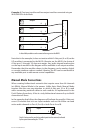
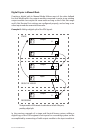
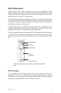
A‑Net merger hubs can be added as need to simplify cabling, extend the
distance between Pro64 modules, and to provide split points and redundant
cable paths.
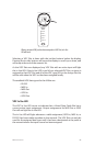
Remember that when using Manual Mode the RCI Remote Control Interface
also needs to have its A‑Net Receive ports set properly in order to edit
channel strip parameters of 6416m modules in the Pro64 network.