


63virtuAl dAtA cAbles
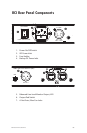
VIRTUAL DATA CABLE PORTS
AC POWER
FUSE: VAC-FAL
IN
OUT
RS-
RESERVED
CONTROL MASTER
–8
IN OUT
ON
RS-
AMP
PIN = GND
VDC
BACKUP POWER
GPIO INPUT
UP= ISOLATED
DN=TTL
– –
Pin 2 Hot
Mic Input Module
B
A
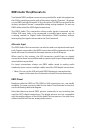
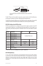
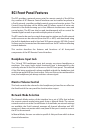
The rst eight switches on the DIP switch block are used to set the RS-232
baud rate.
The RS‑232 port is also used for computer communication with Pro64 devices
for firmware updates and other Managed Mode applications.
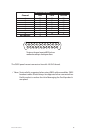
The RS‑232 port on the 6416m uses a 9‑pin DB9 connector and eight of the ten DIP
switches in the DIP switch block (the remainder are used for system functions).
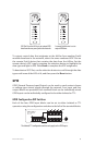
RS-232 Configuration DIP Switches
RS‑232 communication is configured using the first eight switches in the DIP
switch block. Switches 1‑4 set the baud rate and switches 5‑8 are used to set
data, parity, and stop bit options. Switches 9 and 10 are reserved for system
use.
Switch Function Off On
1 Baud Rate bit 3
See Baud Rate chart
2 Baud Rate bit 2
3 Baud Rate bit 1
4 Baud Rate bit 0
5 Data Bits 7 8
6 Parity Low/High No parity Parity
7 Parity Even/Odd Even Odd
8 Stop Bit 1 2
9 Reserved
10 Control Master
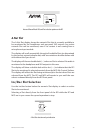
To set a DIP switch to the on position, push it upwards.
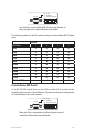
RS-232 Baud Rates
To set a baud rate, determine the appropriate baud rate for data transfer
by referring to the external send/receive devices’ documentation. Set both
devices to communicate using the same baud rate. Finally, set the Pro64
devices to the same baud rate and activate the VDCs using the front‑panel
interface.