


27control MAster
6 416
m
A-NET SLOT
Edit Lock
Managed
Edit
CONTROL
MASTER
ENTER
CANCEL
Gain (dB)
Port A
Port B
Auto
A-NET
TRANSMIT
Manual
VDC SLOT
RS-232
MIDI In
MIDI Out
GPIO In
GPIO Out
ASSIGN
PORT
CLOCK
MASTER
CONTROL
Sample Rate
1 2 3 4 5 6 7 8 9 10 11 12 13 14 15 16
Link
Link Link
Link
Link Link
Link
Link
Mute
Edit
Mute
Edit
Mute
+48VPhase Low CutSAVE RECALL Pad
Ø
Pad
+48V
Ø
Pad
+48V
Ø
Pad
+48V
Ø
Pad
+48V
Ø
Pad
+48V
Ø
Pad
+48V
Ø
Pad
+48V
Ø
Pad
+48V
Edit
Mute
Edit
Mute
Edit
Mute
Edit
Mute
Edit
Mute
Edit
Mute
Edit
Mute Mute Mute
Mute
Edit Edit Edit Edit
Mute
Edit
Mute
Edit
Mute
FUNCTION
Group 4
Group 3
Group 2
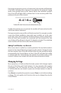
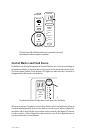
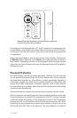
Managed Mode allows the network to be controlled from a computer and
can only be entered from the Control Master.
To manage a Pro64 network with a PC, the PC needs to be connected to the
Control Master using a DB9 null modem cable connected to the RS‑232 port.
The RS‑232 baud rate DIP switches must also be set to the same rate as the
PC application.
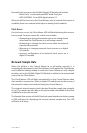
Exiting Managed Mode is also done from the Control Master. Pressing the
lit Ma n a g E d button followed by the En t E r button will return the network to
local control. Attempting to enter or exit Managed Mode from any module
other than the Control Master will cause the Managed button LED to blink to
indicate the error.
Password Protection
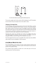
All Pro64 devices ship with a default password. However, a Pro64 network
can be password protected from the Control Master only. Once protected,
the front‑panel interface on all modules is locked, preventing changes to
A‑Net Slots, sample rate, clock source, channel activation, stereo links, and
Virtual Data Cable assignments. Hardware switches, such as gain settings
on input and output modules, and rear‑panel DIP switches are in the analog
domain and are not affected.
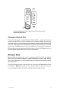
Password protection remains in force even when a system is power cycled.
When a network is password protected, the front panel interface can be used
to get information on channel Slot assignments and VDC routings. Pressing
a channel button will display its Slot assignment in the A‑Net Slot display.
Pressing the VDC inc/dec buttons will cycle through the fourteen VDC Slots,
displaying any port assignments on the current module, as well as the In Use
LED for all active VDC Slots in the network. This query behavior is similar to