


14Pro64 user interFAce
range will result in an error message (the selected channel button, A‑Net Slot
range, and sample rate LEDs will all flash).
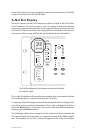
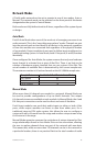
A-Net Slot Display
Since the capacity of the Pro64 network could be as high as 64 A‑Net Slots,
Pro64 hardware I/O devices need a way of routing a selected hardware
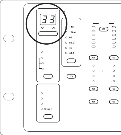
channel to a selected network Slot. In the upper left corner of the front panel
of a Pro64 I/O device, the A‑Net Slot display and its associated inc/dec buttons
are used to select a range of Slots that the hardware device will address.
6 41 6
m
A-NET SLOT
Edit Lock
Managed
Edit
CONTROL
MASTER
ENTER
CANCEL
Gain (dB)
Port A
Port B
Auto
A-NET
TRANSMIT
Manual
VDC SLOT
RS-232
MIDI In
MIDI Out
GPIO In
GPIO Out
ASSIGN
PORT
CLOCK
MASTER
CONTROL
Sample Rate
1 2 3 4 5 6 7 8 9 10 11 12 13 14 15 16
Link
Link Link
Link
Link Link
Link
Link
Mute
Edit
Mute
Edit
Mute
+48VPhase Low CutSAVE RECALL Pad
Ø
Pad
+48V
Ø
Pad
+48V
Ø
Pad
+48V
Ø
Pad
+48V
Ø
Pad
+48V
Ø
Pad
+48V
Ø
Pad
+48V
Ø
Pad
+48V
Edit
Mute
Edit
Mute
Edit
Mute
Edit
Mute
Edit
Mute
Edit
Mute
Edit
Mute Mute Mute
Mute
Edit Edit Edit Edit
Mute
Edit
Mute
Edit
Mute
FUNCTION
Group 4
Group 3
Group 2
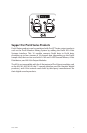
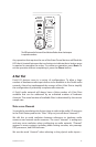
The A-Net Slot display and its inc/dec buttons are used to set the base Slot
for a Pro64 I/O module.
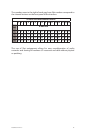
The A‑Net Slot display will show the base number that is associated with the
first hardware input or output channel on an I/O device.
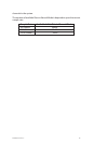
To select an A‑Net Slot range, use the inc/dec buttons below the display. Press
one of the buttons until the desired base Slot range is displayed, and then
press the En t E r button. To return to the current selection without making a
change, press the Ca n C E l button.
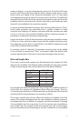
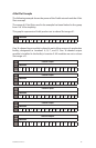
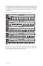
The following tables show examples of the channel‑to‑Slot correlation for
16‑channel Pro64 Series modules in a network running at the 48kHz sample
rate. The numbers in the Slot column will appear in the A‑Net Slot display.