Editing a program Editing a vocoder program
13
Editing a vocoder program
Here’s how to make settings for the vocoder’s carrier,
modulator, and output.
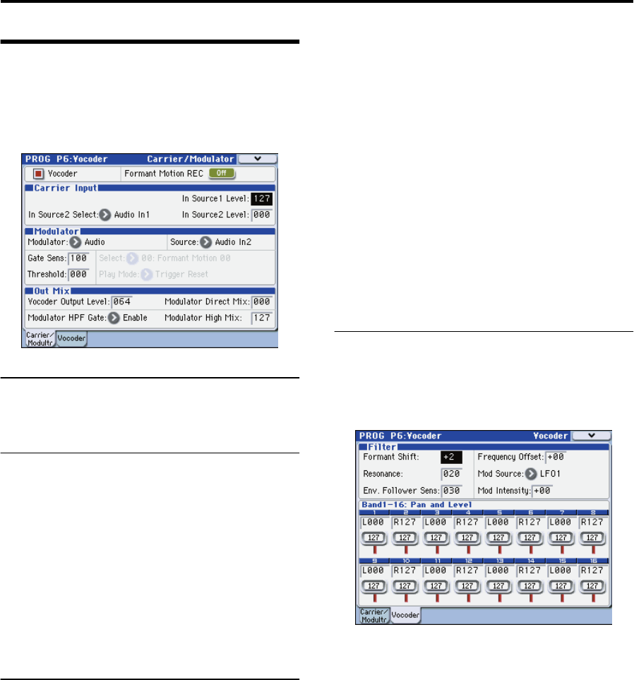
These settings are made in the PROG P6-1: Carrier/
Modulator page.
Vocoder on/off
1. Use “Vocoder” to turn the vocoder on/off. If this is on
(checked), the vocoder will be on.
Carrier Input
As the vocoder’s carrier, you can use two audio signals: the
mono-mixed signal output from the amp section (the signal
before entering the EQ) and the audio signal from an
external input or the AUX bus.
1. Use “In Source 1 Level” to specify the volume of the
oscillator input to the carrier.
Input source 1 is the mono-mixed signal from the amp
section output (the signal before entering the EQ).
2. Use “In Source 2 Select” to select input source 2 to the
carrier.
3. Use “In Source 2 Level” to specify the volume of input
source 2 to the carrier.
Modulator, Out Mix (modulator and
vocoder output settings)
As the modulator of the vocoder, you can use the external
input from the AUDIO INPUT 2 jack, the R-channel of the
S/P DIF or FireWire (if the EXB-FW option is installed), the
audio signal from the AUX bus, or formant motion data.
In this example, we’ll explain how to use a mic connected to
the AUDIO INPUT 2 jack as the modulator.
1. Set “Modulator” to Audio.
2. Set “Source” to Audio In2.
The mic or other device connected to the AUDIO INPUT 2
jack will be the modulator.
Note: If you’re using a signal from the AUDIO INPUT jack as
an input source, make sure that the PROG P1: Program Basic
page Audio In (OSC&Vocoder) Source Audio Inputs (Send
to RADIAS) parameter is set to Analog Input 1/2.
3. Use “Vocoder Output Level” to specify the volume of
the vocoder output.
4. Use “Modulator Direct Mix” to adjust the level of the
modulator input source that is mixed into the vocoder
output.
5. Use “GateSens” to adjust the gate sensitivity. Adjust
this so that the vocoder sound output is not interrupted
in an unnatural way.
6. Use “Threshold” to cut the noise when there is no
input. Raising this setting will make it easier for the
sound to be cut. Adjust this so that noise is not
obtrusive when you’re not speaking into the mic.
7. Use “Modulator HPF Gate” and “Modulator High Mix”
to adjust the high-frequency portion of the input
source that will be mixed into the vocoder output.
Use Modulator HPF Gate to specify whether the high-
frequency portion of the input source mixed into the
vocoder output will be heard only while the internal sound
generator is heard, or whether it will always be heard as
long as there is an input from Source.
Use Modulator High Mix to specify the amount of the high-
frequency portion of the input source that will be mixed into
the vocoder output. Raising this setting will emphasize the
consonants of your voice.
Filter settings
Here you’ll make settings for the modulator’s envelope
follower and the carrier’s band-pass filters (synthesis
filters). These settings are made in the PROG P6-2: Vocoder
page.
Filter (synthesis filter and envelope follower set-
tings)
1. Use “Formant Shift” to change the shift amount for the
band-pass filters. By shifting the filters you can produce
dramatic changes in the character of the vocoder
output.
2. Use “Frequency Offset” to adjust the offset to the cutoff
frequency of the band-pass filters.
You can adjust the filter shift amount in a range of +/-2
steps. In conjunction with Formant Shift, this lets you shift
the cutoff frequency in a range of +/-4 steps. (☞p.44)
3. Use “Resonance” to specify the amount of resonance
for the band-pass filters.
4. Use “Mod Source” to select the modulation source that
will be applied to the cutoff frequency offset
(“Frequency Offset”), and use “Mod Intensity” to
specify the depth of modulation.
5. Use “Env. Follower Sens” to adjust the sensitivity of the
envelope follower.
Higher settings will produce a smoother rise in the vocoder
output and a longer release sound.
Band 1-16: Pan and Level (output level and pan
setting for each band of the synthesis filter)
1. Use “Level” to adjust the output level of each filter.
2. Use “Pan” to adjust the pan of each filter.


